


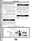
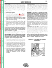

CONNECTION OF THE K488 SG CONTROL
MODULE AND K487 MAGNUM SPOOL GUN
TO THE CLASSIC II (SEE FIGURE C.5.)
1. Shut the welder off.
2. Connect the electrode cable from the SG Control
Module to the “+” terminal of the welder. Connect
the work cable to the “CV–” terminal of the welder.
NOTE: Welding cable must be sized for current
and duty cycle of application.
NOTE: Figure C.5 shows the electrode connect-
ed for positive polarity. To change polari-
ty, shut the welder off and reverse the
electrode and work cables at the Classic II
output terminals.
3. Connect the K867 Universal adapter to the K492
input cable as shown in Figure C.5. Connect the
other end of the adapter to the 14 pin amphenol on
the Classic II.
4. Connect the K492 Input Cable to the SG Control
Module.
5. Set the slide switch on the SG Control Module to
the “Lincoln” position.
Be sure this switch is set to the “Lincoln” (contact clo-
sure) position before attempting to operate the SG
Control Module. Incorrect switch position could result
in damage to the SG Control Module and/or the
CLASSIC II.
6. Place the IDLER switch on the Classic II in the
“HIGH” position.
Any increase of the high idle engine RPM by changing
the governor setting or overriding the throttle linkage
will cause an increase in the AC auxiliary voltage. If
this voltage goes over 140 volts, wire feeder control
circuits may be damaged. The engine governor set-
ting is preset at the factory — do not adjust above
RPM specifications listed in this manual.
7. Adjust wire feed speed at the SG Control Module.
NOTE: For remote control, a K775 remote control
is required.
When the welder is in local control, the electrode is
always “HOT.”
ACCESSORIES
C-8 C-8
CLASSIC II
Return to Section TOC Return to Section TOC Return to Section TOC Return to Section TOC
Return to Master TOC Return to Master TOC Return to Master TOC Return to Master TOC
CAUTION
CAUTION
CAUTION
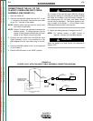
FIGURE C.5
CLASSIC II/K492/K488/K487 SPOOL GUN CONNECTION DIAGRAM
Splice Leads
and Insulate
Insulate Each
Unused Lead
Individually
TO
WORK
14 PIN
AMPHENOL
K487-25
SPOOL
GUN
K488 SG
CONTROL
MODULE
SPARE
82
81
42
41
21
32
31
32
31
22
44
75
76
77
75
76
77
GND GND
GREEN
K492
INPUT CABLE
K775 OPTIONAL
REMOTE CONTROL
K867 UNIVERSAL
ADAPTER PLUG
ELECTRODE CABLE TO
K438 SG CONTROL CABLE
CV-
+
Classic II Output
Terminals are on
Opposite Side