


Return to Section TOC Return to Section TOC Return to Section TOC Return to Section TOC
Return to Master TOC Return to Master TOC Return to Master TOC Return to Master TOC
TROUBLESHOOTING & REPAIR
F-44 F-44
CLASSIC II
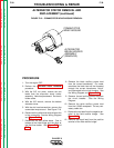
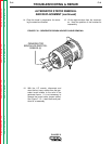
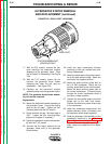
GENERATOR FRAME REMOVAL
AND REPLACEMENT (continued)
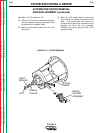
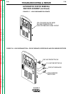
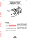
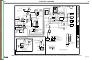
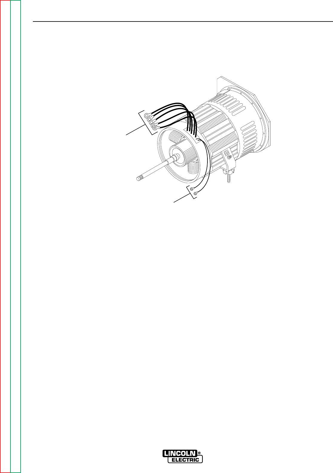
FIGURE F.21 – GENERATOR LEAD AND CABLE CONNECTIONS
SELECTOR
SWITCH
CABLES
BLUE AND
BROWN LEADS
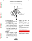
PROCEDURE
1. Turn the engine OFF.
2. Perform the
Alternator Rotor Removal
procedure.
3. Perform the
Alternator Stator Removal
procedure.
4. Cut all necessary cable ties.
5. Disconnect the blue and the brown wires at
the in-line connectors. See Figure F. 21 and
the Wiring Diagram.
6. With the 3/4" wrench, remove the cable from
the positive output terminal.
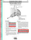
7. Label the five cables that are connected to the
selector switch. Otherwise, you will need to
see the Wiring Diagram during reassembly.
8. With the 1/2" wrench, remove the five cables
connected to the selector switch.
9. Carefully clear all remaining leads and set the
front panel assembly to the left side of the
machine. On later models, remove leads #62
and #58 from the circuit breaker located on
the output terminal assembly.