


Return to Section TOC Return to Section TOC Return to Section TOC Return to Section TOC
Return to Master TOC Return to Master TOC Return to Master TOC Return to Master TOC
TROUBLESHOOTING & REPAIR
F-39 F-39
CLASSIC II
ALTERNATOR STATOR REMOVAL AND
REPLACEMENT (continued)
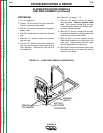
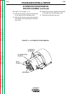
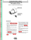
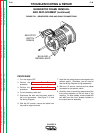
FIGURE F.16 – COMMUTATOR WRAP-AROUND REMOVAL
COMMUTATOR
WRAP-AROUND
ALTERNATOR
BRUSH HOLDER
ASSEMBLY
(REMOVED)
PROCEDURE
1. Turn the engine OFF.
2. Perform the
Alternator Rotor Removal
procedure.
3. With the 3/8" nut driver, remove the two
leads from the alternator brush holder
assembly. Note lead placement. Set brush
holder aside.
4. With the 3/8" wrench, remove the bottom
alternator cover.
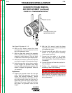
5. With the slot head screwdriver, remove the
commutator wrap-around. See Figure F.16.
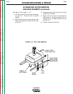
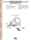
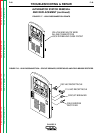
6. Disconnect the yellow and white wires at the
in-line connectors. See the Wiring Diagram
and
Figure F. 17.
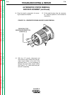
7. Disconnect the two yellow leads. One is
located at the field bridge and the other at
the field fuse holder. See
Figure F.17
and
F.18.
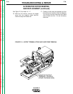
8. Remove the black auxiliary power lead
from the current transformer. On newer
machines the black lead will be threaded
through the current transformer "donut"
and connected to the circuit breaker. See
the Wiring Diagram and
Figure F.18.
9. Remove the red auxiliary power lead from
the circuit breaker. See the Wiring
Diagram.
10. Remove the white auxiliary power lead
from the 115VAC receptacle. Cut any nec-
essary cable ties.
11. Remove the red lead from the negative ter-
minal of the field rectifier bridge. See
Figure F.18.
12. Remove the black lead from the positive
terminal of the field rectifier bridge.