


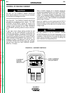
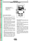
DIESEL ENGINE CONTROLS
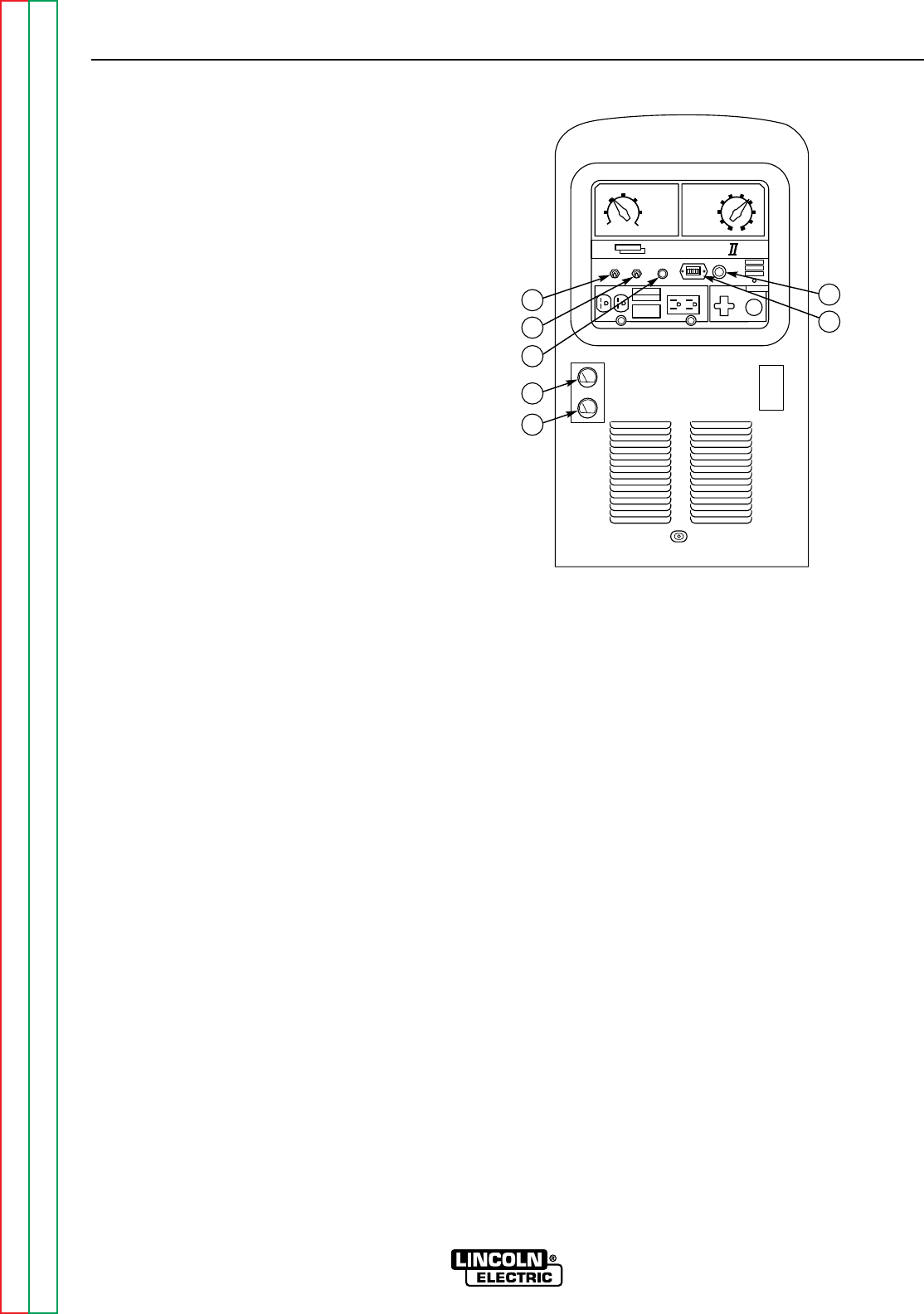
See Figure B.3 for the location of the following fea-
tures:
1. IDLER CONTROL TOGGLE SWITCH: Adjusts the
running speed of the engine. The switch has two
positions, "HIGH" and "AUTO." In "HIGH," the
engine runs continuously at high idle. In "AUTO,"
the idler control works as follows:
Welding: The engine accelerates to high speed
when the electrode touches the work and strikes a
welding arc. The engine returns to low idle approx-
imately 15 seconds after welding stops, as long as
no auxiliary power is being drawn.
Auxiliary Power: The engine accelerates to high
speed when power is drawn at the receptacles for
lights or tools. The engine returns to low idle
approximately 15 seconds after demand for
auxiliary power stops.
2. IGNITION CONTROL TOGGLE SWITCH: Has
two positions, ON and OFF. When the switch is in
the ON position, the diesel engine can be started
by pressing the START pushbutton. When the
switch is placed in the OFF position, the engine
stops.
3. ENGINE PROTECTION WARNING LIGHT: Lights
when the engine protection system (an internal kill
switch) has shut down the engine. The system
activates in response to low oil pressure or high oil
temperature. If the light comes on during
startup cranking or after the engine starts, the
IGNITION switch must be placed in the OFF
position to reset the engine protection system.
4. START PUSHBUTTON: Press this button to start
the diesel engine. The IGNITION switch must be
in the ON position.
NOTE: If you press the START pushbutton when
the engine is running, you may damage the engine
flywheel gear or starter motor.
5. ENGINE HOUR METER: Records engine running
time. Use the meter to determine when to
perform required maintenance.
6. AMMETER: Shows whether the charging circuit
is performing its job of charging the battery when
the engine is running. The meter will register
discharge during starting, but then the needle
should return to a position slightly toward positive
during running. The needle will hold position in the
center when the engine stops.
7. OIL PRESSURE GAUGE: Indicates engine oil
pressure. If no oil pressure shows on the gauge
within 30 seconds after startup, the engine should
be stopped by placing the IGNITION switch in the
OFF position.
OPERATION
B-7 B-7
CLASSIC II
Return to Section TOC Return to Section TOC Return to Section TOC Return to Section TOC
Return to Master TOC Return to Master TOC Return to Master TOC Return to Master TOC
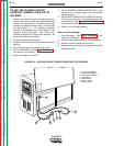
FIGURE B.3 – DIESEL ENGINE CONTROLS
220
MAX.
240-160
190-120
130-80
90
MIN.
90
80
70
60 50
40
30
20
10100
CURRENTRANGE
SELECTION
IDLER IGNITION
START
REMOTE
CONTROL
ENGINE
PROTECTION
C
lassic
115 VOLTAC230 VOLTAC
FINE CURRENT
ADJUSTMENT
4
6
1
7
2
3
5
1. IDLER CONTROL TOGGLE SWITCH
2. IGNITION TOGGLE SWITCH
3. ENGINE PROTECTION WARNING LIGHT
4. START PUSHBUTTON
5. ENGINE HOUR METER
6. AMMETER
7. OIL PRESSURE GAUGE