


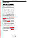
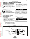
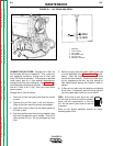
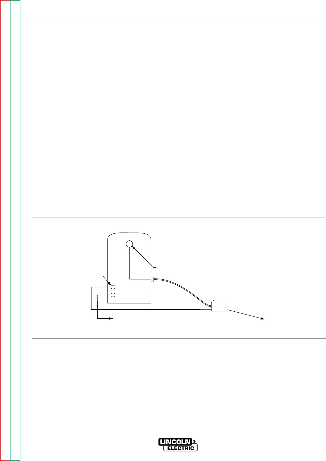
CONNECTION OF THE LN-25 TO THE
CLASSIC II “ACROSS THE ARC”
(SEE FIGURE C.4.)
1. Shut the welder off.
2. Connect the electrode cable from the LN-25 to the
“+” terminal of the welder. Connect the work cable
to the “CV–” terminal of the welder.
NOTE: Welding cable must be sized for current
and duty cycle of application.
NOTE: Figure C.4 shows the electrode connect-
ed for positive polarity. To change polari-
ty, shut the welder off and reverse the
electrode and work cables at the Classic II
output terminals. Reverse the LN-25
polarity switch.
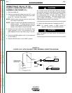
3. Attach the single lead from the LN-25 control box
to the work using the spring clip on the end of the
lead. This is only a control lead — it carries no
welding current.
4. Place the IDLER switch in the “HIGH” position.
5. Adjust wire feed speed and voltage at the LN-25.
ACCESSORIES
C-7 C-7
CLASSIC II
Return to Section TOC Return to Section TOC Return to Section TOC Return to Section TOC
Return to Master TOC Return to Master TOC Return to Master TOC Return to Master TOC
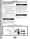
FIGURE C.4
CLASSIC II/LN-25 ACROSS THE ARC CONNECTION DIAGRAM
Classic II Output
Terminals are on
Opposite Side
TO
WORK
14 PIN
AMPHENOL
WORK CLIP
LEAD TOWORK
LN-25 WIRE FEEDER
WITH K444-2 REMOTE
VOLTAGECONTROL OPTION
ELECTRODE CABLE
CV-
+