


Return to Section TOC Return to Section TOC Return to Section TOC Return to Section TOC
Return to Master TOC Return to Master TOC Return to Master TOC Return to Master TOC
OPERATION
B-5 B-5
CLASSIC II
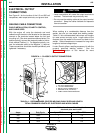
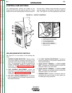
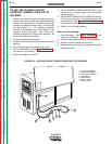
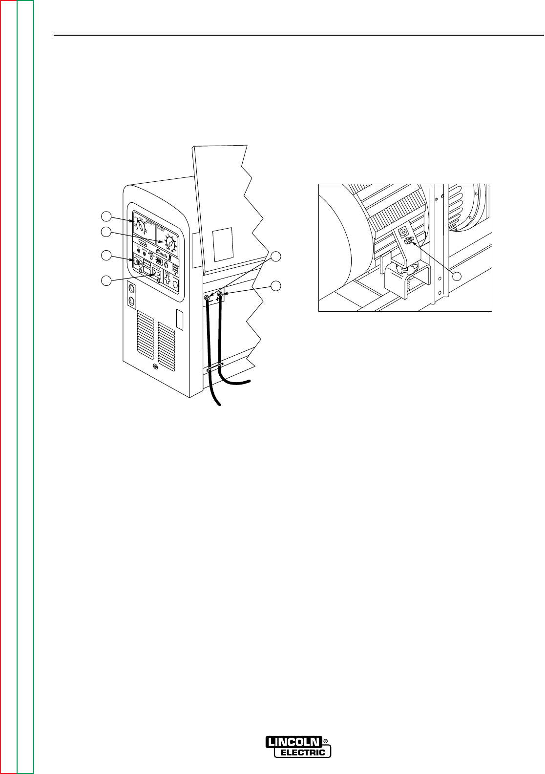
FIGURE B.1 – OUTPUT CONTROLS
1. CURRENT RANGE SELECTOR
2. FINE CURRENT ADJUSTMENT
3. 230 VOLT RECEPTACLE
4. 115 VOLT RECEPTACLE
5. WELD OUTPUT TERMINAL (–)
6. WELD OUTPUT TERMINAL (+)
7. GROUND STUD
WELDER/GENERATOR CONTROLS
See Figure B.1 for the location of the following fea-
tures:
1. CURRENT RANGE SELECTOR: Selects continu-
ous current output for constant current stick or TIG
applications and constant voltage wire feed applica-
tions. The amperages on the dial correspond to the
average amperages needed for specific Lincoln
welder rods. See
Control of Welding Current
for
more information.
2. FINE CURRENT ADJUSTMENT: Allows fine
adjustment of current within the selected output
range. See
Control of Welding Current
for more
information.
3. 230 VOLT DUPLEX RECEPTACLE: Connection
point for supplying 230 volt power to operate one or
two electrical devices.
4. 115 VOLT DUPLEX RECEPTACLE: Connection
point for supplying 115 volt power to operate one or
two electrical devices.
5. WELD OUTPUT TERMINAL (–) WITH FLANGE
NUT: Provides the connection point for either the
electrode holder or the work cable.
6. WELD OUTPUT TERMINAL (+) WITH FLANGE
NUT: Provides the connection point for either the
electrode holder or the work cable.
7. GROUND STUD: Provides a connection point for
connecting the machine case to earth ground for
the safest grounding procedure.
CONTROLS AND SETTINGS
The welder/generator controls are located on the
Output Control Panel of the machine case front. Diesel
engine idler control and start/stop controls are also on
the case front. Welding output terminals and ground
stud are located on the machine right side, under the
door. See Figure B.1 and the explanations that follow.
3
1
2
6
5
4
7