


FUEL FILTER: Inspect the fuel filter daily. Drain any
accumulated water from the engine fuel filter/water
separator daily. Change the fuel filter after the first 50
hours of operation and every 1000 hours thereafter.
Dust and dirt in the fuel system can cause the injection
pump and injection nozzle to wear quickly. Change the
fuel filter as follows:
1. Close the fuel stopcock.
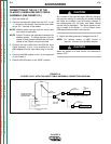
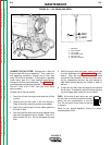
2. Loosen the fuel filter cartridge (see
Figure D.1
) with
a removal tool and spin the cartridge off. Catch any
escaping fuel in an appropriate container.
3. Clean the sealing surface of the filter carrier. Apply
a light film of oil or diesel fuel to the rubber gasket
of the new fuel filter cartridge.
4. Screw the new cartridge into position finger tight
until the gasket is evenly seated. Then turn it down
another 1/2 turn. Do not overtighten the new filter.
5. Open the fuel stopcock. Check the assembly for
leaks.
Order Deutz fuel filter #117-4482 from your local Deutz
Service Center. A fuel filter element without the water
separator may be used in place of the standard ele-
ment. Order Deutz #117-4696.
The fuel system on the Deutz engine is self priming.
You do not have to bleed the system.
AIR CLEANER: The Deutz diesel engine is equipped
with a dry type air filter. Inspect the air cleaner daily -
more often in dusty conditions. Never apply oil to the
air cleaner. Service the air cleaner as follows:
1. Remove the dust cup from the bottom of the air
cleaner housing. Clean out any accumulated dust.
2. Loosen the wing nut and remove the filter element.
3. If dust is sticking to the dust collector element, blow
compressed air through it from the inside out.
Turn the element as you apply air. Air pressure
should be under 686 kPa (7 kgf/cm
2
, 99 psi).
4. Check the element for damage before reassem-
bling the air cleaner. Replace the element if it
appears damaged. The air cleaner element part
number is Donaldson #181050 or Nelson
#70206N.
COOLING SYSTEM: The Deutz diesel engine is air
cooled. Clean the engine cooling system periodically
to prevent clogging the air passages on the cylinder
heads and oil cooler and overheating the engine.
Consult the Engine Operation Manual. It is important
to locate the welder to provide an unrestricted flow of
clean, cool air.
BEARINGS: The Classic II is equipped with double-
shielded ball bearings having sufficient grease to last
indefinitely under normal service. Where the welder is
used constantly or in excessively dirty locations, it may
be necessary to add one half ounce of grease per year.
A pad of grease one inch wide, one inch long, and one
inch high weighs approximately one half ounce. Over-
greasing is far worse than insufficient greasing.
When greasing the bearings, keep all dirt out of the
area. Wipe the fittings completely clean and use clean
equipment. More bearing failures are caused by dirt
introduced during greasing than from insufficient
grease.
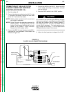
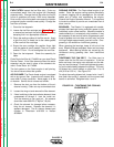
TIGHTENING THE FAN BELT: Fan Belts tend to
loosen after the first 50 hours of operation. If the fan
belts are loose, the engine can overheat and the bat-
tery can lose its charge. Check belt tightness by press-
ing on the belt midway between the pulleys. The cool-
ing blower belt should deflect no more than 10 to 15
mm (0.28 to 0.35 in.). See Figure D.2.
To adjust the cooling blower belt, loosen bolts 1 and 2,
then push idler pulley 3 outward until the correct belt
tension is achieved. Retighten bolts 1 and 2.
MAINTENANCE
D-4 D-4
CLASSIC II
Return to Section TOC Return to Section TOC Return to Section TOC Return to Section TOC
Return to Master TOC Return to Master TOC Return to Master TOC Return to Master TOC
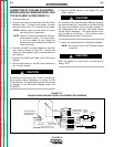
FIGURE D.2 – TIGHTENING THE COOLING
BLOWER BELT