


Return to Section TOC Return to Section TOC Return to Section TOC Return to Section TOC
Return to Master TOC Return to Master TOC Return to Master TOC Return to Master TOC
TROUBLESHOOTING & REPAIR
F-42 F-42
CLASSIC II
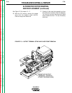
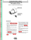
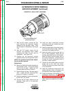
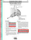
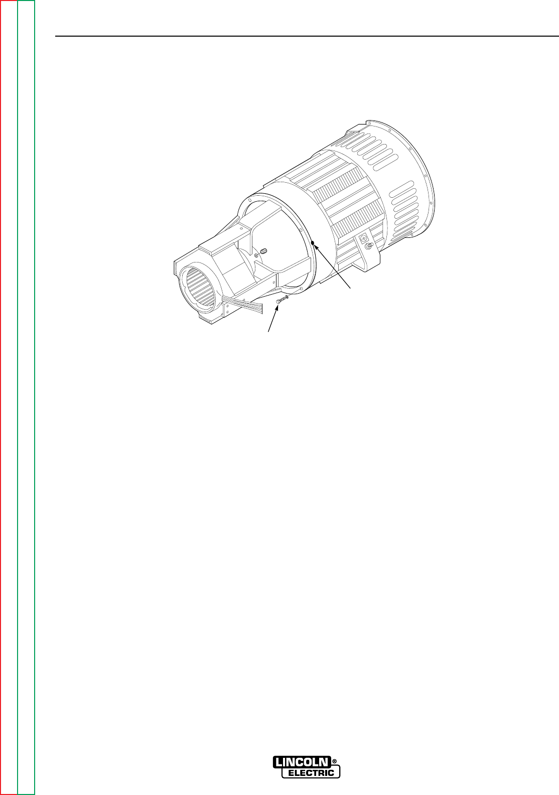
FIGURE F.20 - DRILL SPOT LOCATIONS
DRILL SPOT
STATOR/ENDBRACKET
MOUNTING BOLT
17. With the 5/8" wrench, remove the four
bolts mounting the stator/end bracket
assembly to the generator frame. Note
the "drill spot" for reassembly. See Figure
F.20.
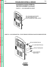
18. With the 7/16" wrench, loosen (do not
remove) the generator brush holder
clamping bolt. Note the drill spot for
reassembly . See Figure F.20.
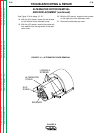
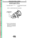
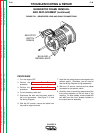
19. Carefully pry the stator/end bracket
assembly away from the generator frame.
NOTE: The generator brush holder assem-
bly will also be removed.
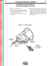
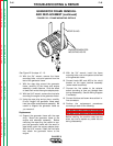
Replacement
20. Mount the stator/end bracket assembly to
the generator frame. Line up the mating
parts at the drill spot. Tighten the four
mounting bolts with the 5/8" wrench.
21. Check armature air gap. Minimum gap is
.035." Loosen the four mounting bolts;
adjust and re-tighten if necessary.
22. Tighten the generator brush holder assem-
bly with the 7/16" wrench.
23. Connect the four heavy cables from the
generator frame coils to the generator
brush holders.
24. Install the eight commutator brushes
according to how you marked their posi-
tions at disassembly.
25. Attach the black lead to the positive termi-
nal of the field rectifier bridge. Attach the
red lead to the negative terminal.
26. Attach the white auxiliary power lead to
the 115 VAC receptacle. Attach the red
auxiliary power lead to the circuit breaker.
Attach the black auxiliary power lead to
the current transformer. Thread the lead
through the current transformer donut if
you have a newer machine.
27. Connect the two yellow leads to the field
bridge and to the field fuse holder.
Connect the white and yellow wires at the
in-line connectors.
28. Install the commutator wrap-around, the
bottom alternator cover, the battery, and
the alternator brush holder assembly.
29. Install the alternator rotor according to the
reassembly directions in the
Alternator
Rotor Removal and Replacement
pro-
cedure. Before installing the case top and
sides, replace any cable ties cut for disas-
sembly.
ALTERNATOR STATOR REMOVAL
AND REPLACEMENT (continued)