


Return to Section TOC Return to Section TOC Return to Section TOC Return to Section TOC
Return to Master TOC Return to Master TOC Return to Master TOC Return to Master TOC
TROUBLESHOOTING & REPAIR
F-21 F-21
CLASSIC II
IDLER SOLENOID TEST (continued)
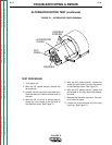
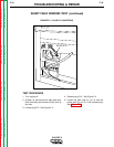
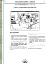
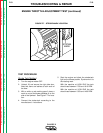
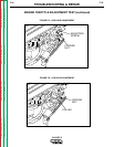
FIGURE F.6 - SOLENOID/HARNESS LEAD CONNECTIONS
LEADS #56, #57
TEST PROCEDURE
1. Turn engine off.
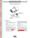
2. Unlatch, lift and secure the right side door.
Note that there are latches at both ends of
the door.
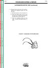
3. Locate and separate the two in-line spade
connectors that attach the solenoid leads to
the wiring harness leads (#56 and #57). See
Figure F.6 and the Wiring Diagram.
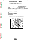
4. Using the external voltage supply, apply
12VDC to the idler solenoid leads. The sole-
noid should activate.
NOTE: WHEN THE ENGINE IS NOT RUN-
NING, THE SOLENOID MAY REQUIRE A
SLIGHT MECHANICAL ASSISTANCE TO
OPERATE.
5. The solenoid should deactivate when the
12VDC is removed.
6. If the solenoid does not operate properly,
check for a mechanical restriction in the link-
age or a missing spring.
7. If the linkage is intact and the solenoid does
not operate correctly when 12VDC is
applied, the solenoid may be faulty.
Replace.
8. When the test is complete and the problem
repaired, be sure to reconnect the two spade
connectors to leads #56 and #57 on the
wiring harness.
9. Close and latch the right side door.