


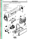
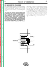

ENGINE, GENERATOR ARMATURE
AND FRAME, ALTERNATOR STA-
TOR AND ROTOR (CONTINUED)
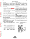
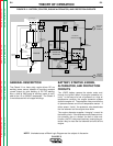
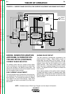
CURRENT RANGE SELECTOR
The selector switch acts as a coarse current adjust-
ment by allowing for varying amounts of series wind-
ings to be included in the welding current path. The
series coils and selector switch are connected in series
with the negative output terminal.
FINE CURRENT ADJUSTMENT
The field rheostat control functions as a fine output cur-
rent adjustment by controlling the current through the
shunt windings. This controls the amount of magnet-
ism created in the shunt field windings. Open circuit
weld voltage can also be controlled by the field rheo-
stat control.
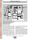
ENGINE IDLER CIRCUIT
The idler solenoid is mechanically connected to the
engine governor linkage. When welding current is
being drawn, the reed switch CR2 is closed. This sig-
nals the idler PC board to release (deactivate) the idler
solenoid, which then lets the machine go to a high
speed condition. Also, when auxiliary power is being
used, the current is passed through the current trans-
former. This signals the idler PC board to release the
idler solenoid.
When welding ceases or the auxiliary load is removed,
a preset time delay of about 15 seconds starts. After
approximately 15 seconds the idler PC board activates
the idler solenoid, and the machine will return to a low
speed condition.
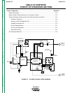
THEORY OF OPERATION
E-4 E-4
CLASSIC II
Return to Section TOC Return to Section TOC Return to Section TOC Return to Section TOC
Return to Master TOC Return to Master TOC Return to Master TOC Return to Master TOC
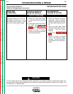
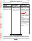
NOTE: Unshaded areas of Block Logic Diagram are the subject of discussion.
FIGURE E.4 – CURRENT RANGE SELECTOR, FINE CURRENT ADJUSTMENT AND ENGINE IDLER CIRCUIT
NEGATIVE
OUTPUT
TERMINAL
POSITIVE
OUTPUT
TERMINAL
115 & 230VAC
RECEPTACLES
CURRENT
TRANSFORMER
FIELD
RECTIFIER
FLASHING
RESIDUAL
MAGNETISM
ALTERNATOR STATOR
ROTOR
SLIP
RINGS
ARMATURE
SHAFT
GENERATOR
ARMATURE
BRUSHES
&
COMMUTATOR
GENERATOR
FRAME
SERIES
COILS
INTERPOLE
COILS
SHUNT
WINDINGS
GENERATOR
FIELD CONTROL
FIELD
MECHANICAL
COUPLING
REED
RELAY
CR2
SELECTOR
SWITCH
IDLER
BOARD
IDLER
SOLENOID
OIL
PRESSURE
SENSOR
OIL
TEMPERATURE
SENSOR
FUEL
SOLENOID
RELAY
CR1
ENGINE
ALTERNATOR
STARTER
MOTOR
BATTERY
ENGINE
PROTECTION
RELAY
IGNITION
SWITCH
ON LATER MODELS
PROTECTION AND IDLER CIRCUITS
ARE ON ONE PC BOARD
(NOT PRESENT
ON LATER MODELS)