


ELECTRIC SHOCK can kill.
• With power applied,
there are high voltages
inside the wire feeder.
Do not reach into the
wire feeder or touch any
internal part of the wire
feeder while power is
applied.
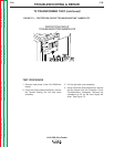
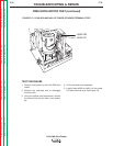
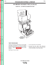
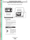
6. Apply input power to the LN-9 GMA and test
for 15VDC at leads #525(+) to #510(-). This
is the supply voltage from the control PC
board to the hall effect module. If the correct
voltage is present, proceed to the next step.
If the voltage is missing, check the wiring
and perform the
General Power Supply
Test.
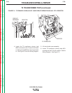
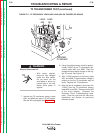
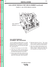
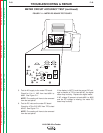
7. With the gun trigger activated or the gun ter-
minals jumpered together (see the Wiring
Diagram), check leads #555(+) to #510(-) for
the presence of between 4.5 - 10.5VDC.
(The motor must be running.) This is the
feedback voltage from the hall effect module
to the control PC board. This voltage is
dependent upon motor speed. If the feed-
back voltage is missing or does not vary with
motor speed, the hall effect module may be
faulty.
TROUBLESHOOTING & REPAIR
F-36 F-36
LN-9 GMA Wire Feeder
Return to Section TOC Return to Section TOC Return to Section TOC Return to Section TOC
Return to Master TOC Return to Master TOC Return to Master TOC Return to Master TOC
WARNING
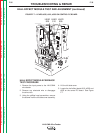
HALL EFFECT MODULE TEST AND ALIGNMENT (continued)