


MAKING A TEST WELD AND
ADJUSTING LN-9 GMA RESPONSE
AND STARTING CHARACTERISTICS
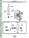
ADJUST THE POWER SOURCE
DC-250, DC-400, or DC-600
1. Connect electrode lead to terminal of desired
polarity.
2. Set toggle switch to same polarity as the electrode
cable connection.
3. Set toggle switch to "Output Control Remote."
4. Set mode switch to the desired position for the
process to be used.
CV-400, CV-500-I
1. Connect electrode lead to terminal of desired
polarity.
2. Connect #21 control lead to the work polarity ter-
minal (+21 or -21), at the terminal strip, matching
the same polarity as the work cable connection.
3. Set toggle switch to "Output Control Remote."
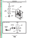
PULSE POWER 500, DC650 PRO, V300
Refer to each machine Instruction Manual. The LN-9
GMA requires the K442-1 Pulse Power Filter Kit. (See
the
Accessories
section of this manual.)
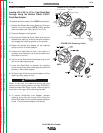
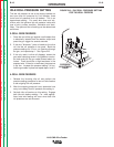
ADJUST THE LN-9 GMA CONTROLS
1. Set the "Electrode Polarity" switch to same polarity
as the electrode lead.
2. Check that "Feed Direction" is set to forward.
3. Set the "Trigger Interlock" switch as desired.
4. Set the "Meter Reading" switch to "Wire Speed"
and adjust the "Wire Speed" rheostat so the meter
reads the desired wire feed speed.
5. Set the "Meter Reading" switch to "Volts" and
adjust the "Volts" rheostat so the meter reads the
desired arc voltage. IMPORTANT: Make certain
this setting is within the voltage output range of the
power source setting.
6. Load the LN-9 GMA with electrode.
OPERATION
B-19 B-19
LN-9 GMA Wire Feeder
Return to Section TOC Return to Section TOC Return to Section TOC Return to Section TOC
Return to Master TOC Return to Master TOC Return to Master TOC Return to Master TOC