


F-68 F-68
LN-9 GMA Wire Feeder
Return to Section TOC Return to Section TOC Return to Section TOC Return to Section TOC
Return to Master TOC Return to Master TOC Return to Master TOC Return to Master TOC
TROUBLESHOOTING & REPAIR
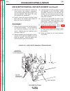
DRIVE MOTOR REMOVAL AND REPLACEMENT (continued)
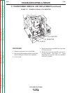
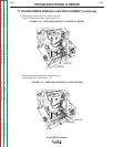
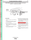
15. With the slot head screwdriver, remove the
three screws, lock washers, flatwashers,
and insulators holding the drive motor to the
gear box assembly. See Figure F.25. Note
their positions for reassembly.
16. Carefully remove the motor and plate. Note
which side of the insulator motor faces the
wire drive rollers for reassembly.
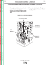
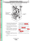
REASSEMBLY
17. Attach the drive motor and insulator plate to
the gear box assembly. Use the insulators
and mounting hardware from step 16,
above. Replace gear box inspection plate
removed in step 14.
18. Attach the glastic mounting board and mylar
insulator to the gear box assembly with the
bolts and washers. Install the copper reed
switch energizer previously removed.
19. From the right side, slide the motor and gear
box assembly into the LN-9 GMA. Attach
the glastic mounting to the floor with the
screws. Four-roll units have nuts and wash-
ers. Attach the gas hose and clamp to the
brass inlet connector.
20. Connect motor leads #539 and #541 to their
quick-connectors. Attach the green motor
ground lead. Install any cable ties cut earli-
er or tape the harness as needed.
21. Install the hall effect module. See the
Hall
Effect Module Alignment
procedure.
22. Install the 9-pin amphenol and the R1 resis-
tor. Be sure to position the resistor insula-
tors properly.
23. Close and fasten the left cover assembly
with screws.
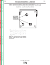
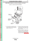
FIGURE F.25 – DRIVE MOTOR REMOVAL FROM GEAR BOX
GEAR BOX
(INSPECTION
PLATE REMOVED)
MOTOR
MOUNTING
SCREWS (3)
DRIVE MOTOR