


INSTALLATION
A-12 A-12
LN-9 GMA Wire Feeder
Return to Section TOC Return to Section TOC Return to Section TOC Return to Section TOC
Return to Master TOC Return to Master TOC Return to Master TOC Return to Master TOC
MACHINE GROUNDING
LN-9 GMA wire feeders are grounded to the power
source through the input cable. The power source
grounding cable must be properly connected to electri-
cal ground. See your power source operating manual
for details.
WORK CABLE CONNECTION
Connect a work lead of sufficient size and length
between the proper output terminal on the power
source and the work. See Table A-1. Be sure the con-
nection to the work makes tight metal-to-metal electri-
cal contact. Poor work lead connections can activate
the grounding lead protector and/or result in poor weld-
ing performance.
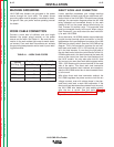
TABLE A.1 – WORK CABLE SIZES
Current
Copper Work Cable Size, AWG
60% Duty Cycle
Up to 50' length 50'-100' Iength
300 Amps 0 00
400 Amps 00 000
500 Amps 00 000
600 Amps 000 0000
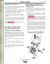
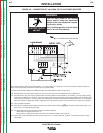
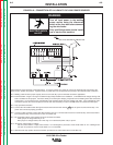
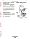
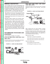
DIRECT WORK LEAD CONNECTION
Lincoln specified procedures give voltage readings
taken between the work and the gun cable brass con-
nection block of the LN-9 GMA. To match these voltage
readings, the connection diagrams show the #21 lead
being extended and connected directly to the work
instead of #21 on the power source terminal strip (or
Dual Process Kit terminal strip). This extended lead
must be connected directly to the work. When using a
Dual Process Kit, you must extend the lead individual-
ly for each LN-9 GMA.
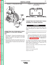
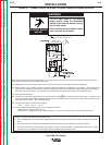
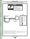
As an alternative, LN-9 GMA models are provided with
a quick-connect terminal splice connection in the #21
lead between the input Amphenol connector of the LN9
GMA and its polarity switch. See the LN-9 GMA wiring
diagram. This in-line connection consists of a red insu-
lated male and female .250 x .032 terminal pair locat-
ed in the lead harness. It runs along the right side of
the wire feed motor inside the control section of the LN-
9 GMA models and in the lead harness at the lower left
corner of the control box (near the input Amphenol) of
the LN-9F models. You may also open this #21 lead
and connect your own direct work lead equipped with a
.250 x .032 female quick-connect terminal to the male
side of the splice. This direct work lead connection
must be tape insulated, strain-relieved, and routed out-
side the LN-9 GMA control box to be connected direct-
ly to the work.
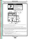
With either direct work lead connection method, the
LN-9 GMA regulates the power source to hold the arc
voltage constant, even with voltage drops in the elec-
trode lead, work lead, or work lead connection. If the
direct work lead becomes disconnected from the work,
the LN-9 GMA wire feeder will stop welding shortly
after the arc is struck. See the topic "
Circuit
Protection and Automatic Shutdown"
in the
Operation
section of this manual.