


F-65 F-65
LN-9 GMA Wire Feeder
Return to Section TOC Return to Section TOC Return to Section TOC Return to Section TOC
Return to Master TOC Return to Master TOC Return to Master TOC Return to Master TOC
TROUBLESHOOTING & REPAIR
DRIVE MOTOR REMOVAL AND REPLACEMENT (continued)
PROCEDURE
1. Remove input power to the LN-9 GMA wire
feeder.
2.
Using the phillips head screwdriver, remove the
screws holding the left side cover assembly.
3. Lift the cover assembly.
4. With the slot head screwdriver and the 3/8"
wrench, remove the R1 (2 ohm) resistor.
Note the position of the insulators for
reassembly.
5. Using the phillips head screwdriver, remove
the 9 pin amphenol connector.
6. Set the resistor and the amphenol connector
aside as far as the lead lengths will allow.
This is necessary to gain access to one of
the three screws that mount the glastic base
to the floor assembly.
7. Remove the hall effect module. (See the
Hall Effect Module Alignment
procedure).
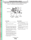
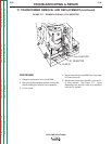
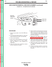
8. Locate and remove motor leads #539 and
#541 at their quick-connectors. Note lead
placement for reassembly. See Figure F.22.
9. Remove the green motor ground lead. Cut
or untape any necessary cable ties. See
Figure F.22.
10. Using the slot head screwdriver, remove the
gas hose and clamp from the brass inlet
connector.
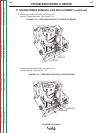
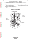
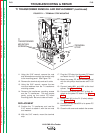
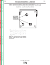
FIGURE F.22 – TOP MOTOR PLATE SCREWS
MOTOR
GROUND
LEAD
LEAD 539
LEAD 541