


INSTALLATION
A-5 A-5
LN-9 GMA Wire Feeder
Return to Section TOC Return to Section TOC Return to Section TOC Return to Section TOC
Return to Master TOC Return to Master TOC Return to Master TOC Return to Master TOC
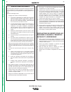
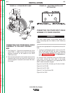
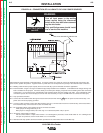
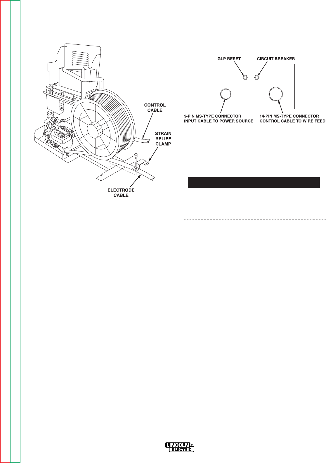
FIGURE A.2 – STRAIN RELIEF CLAMP
CONNECTING THE POWER INPUT CABLE
ASSEMBLY TO THE LN-9F CONTROL
BOX
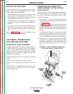
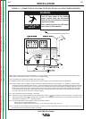
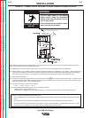
1. See Figure A.3. Connect the polarized plug of the
K196, K595, or K596 control cable to the mating
MS-type connector on the bottom of the LN-9F
GMA control box.
2. Bolt the electrode lead from the power source to the
electrode lead to the wire feed unit using the nut
and bolt supplied. Insulate the connection with elec-
trical tape.
CONNECTING THE POWER INPUT CABLE
ASSEMBLY TO POWER SOURCES
Turn input supply power to the power source OFF
before connecting the LN-9 GMA or LN-9F GMA wire
feeder.
Connect to an appropriate Lincoln power source as fol-
lows:
1. If using a multipurpose source (such as the DC-
250, DC-400 and DC-600), be sure it is properly
set for the welding process being used. See the
topic
"Making a Test Weld,"
in the
Operation
sec-
tion of this manual.
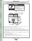
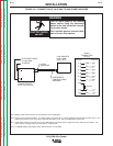
For terminal strip connections using the K196 power
input cable, connect the input cable to the power
source exactly as specified on the appropriate LN-9
GMA model connection diagram:
Figure A.4 for DC-250, DC-400 and CV-400, CV-500 l
Figure A.5 for DC-600
Figure A.6 for DC-1000
Figure A.7 for Pulse Power 500
Figure A.8 for V300
FIGURE A.3 – LN-9F GMA CONTROL BOX
BOTTOM VIEW
WARNING