


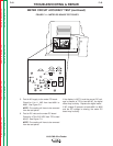
HALL EFFECT MODULE
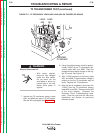
ALIGNMENT TEST PROCEDURE
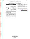
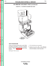
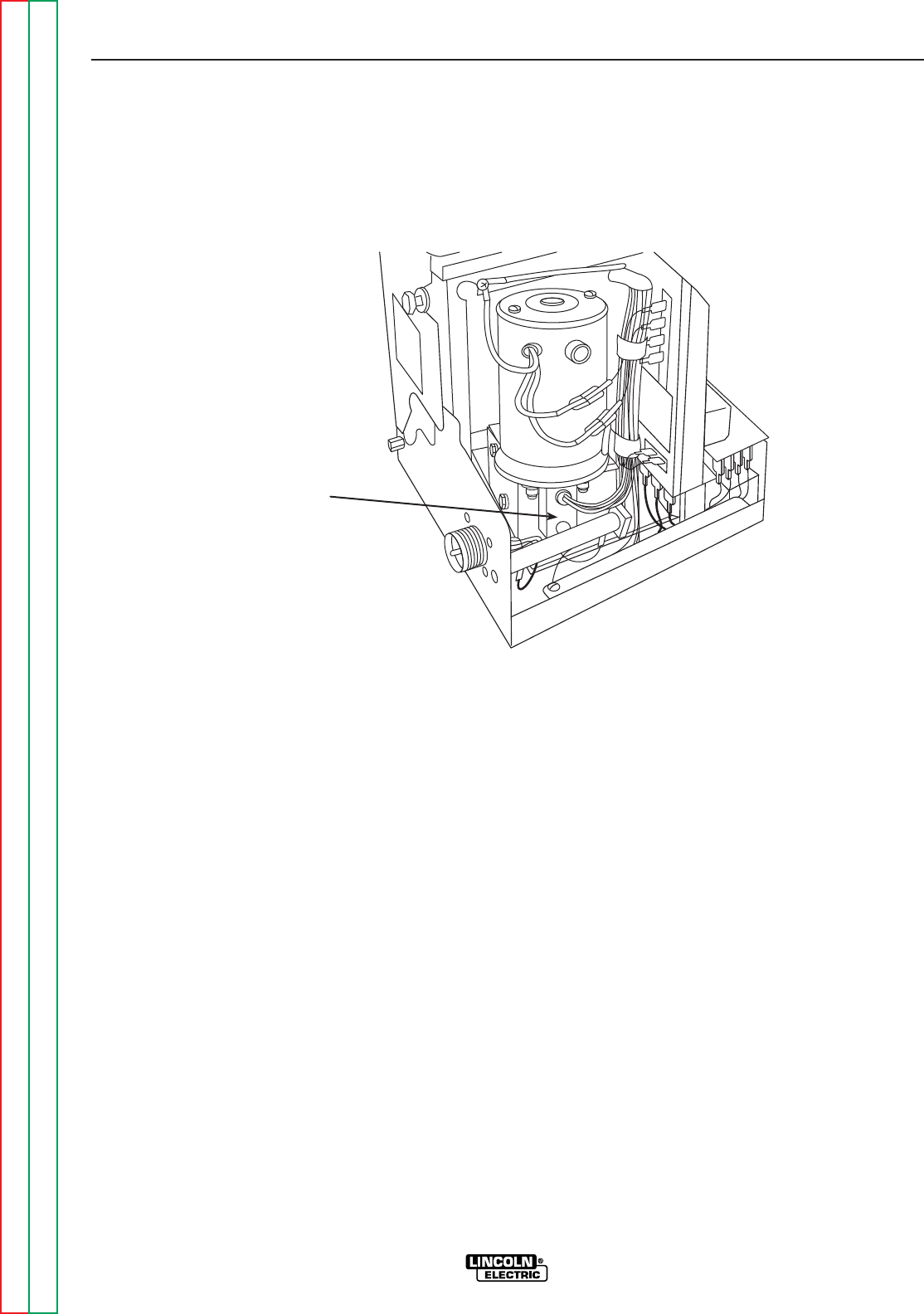
The LN-9 GMA wire speed sensor is a three
lead hall-effect device encased in an externally
threaded housing. It is screwed into a mounting
plate on the motor side of the wire drive gear-
box. See Figure F.8.
1. Remove the input power to the LN-9 GMA.
2. Check that the module mounting plate is
screwed securely to the side of the gearbox
and seated flush against the top surface.
3. Gently screw the hall effect module into the
mounting plate until it just touches and stops
against the rotating part inside the gearbox.
4. Back the module out 1/2 turn. Then, using
the 9/16” wrench, carefully snug the module
locknut without rotating the module position.
5. After the hall effect module tests are com-
pleted, remove the jumper from the gun ter-
minals (if used). Close the left side case
cover assembly and reattach the screws.
INSTALLATION
F-37 F-37
LN-9 GMA Wire Feeder
Return to Section TOC Return to Section TOC Return to Section TOC Return to Section TOC
Return to Master TOC Return to Master TOC Return to Master TOC Return to Master TOC
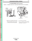
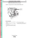
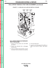
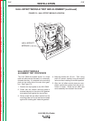
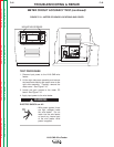
HALL EFFECT MODULE TEST AND ALIGNMENT (continued)
FIGURE F.8 – HALL EFFECT MODULE LOCATION
HALL-EFFECT
MODULE