


TROUBLESHOOTING & REPAIR
F-67 F-67
LN-9 GMA Wire Feeder
Return to Section TOC Return to Section TOC Return to Section TOC Return to Section TOC
Return to Master TOC Return to Master TOC Return to Master TOC Return to Master TOC
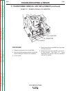
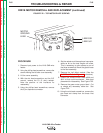
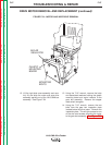
12. Lift the right side cover assembly and care-
fully lift and slide the motor and wire drive
assembly partially out of the LN-9 GMA box
assembly. See Figure F.24.
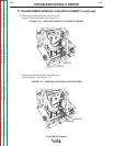
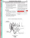
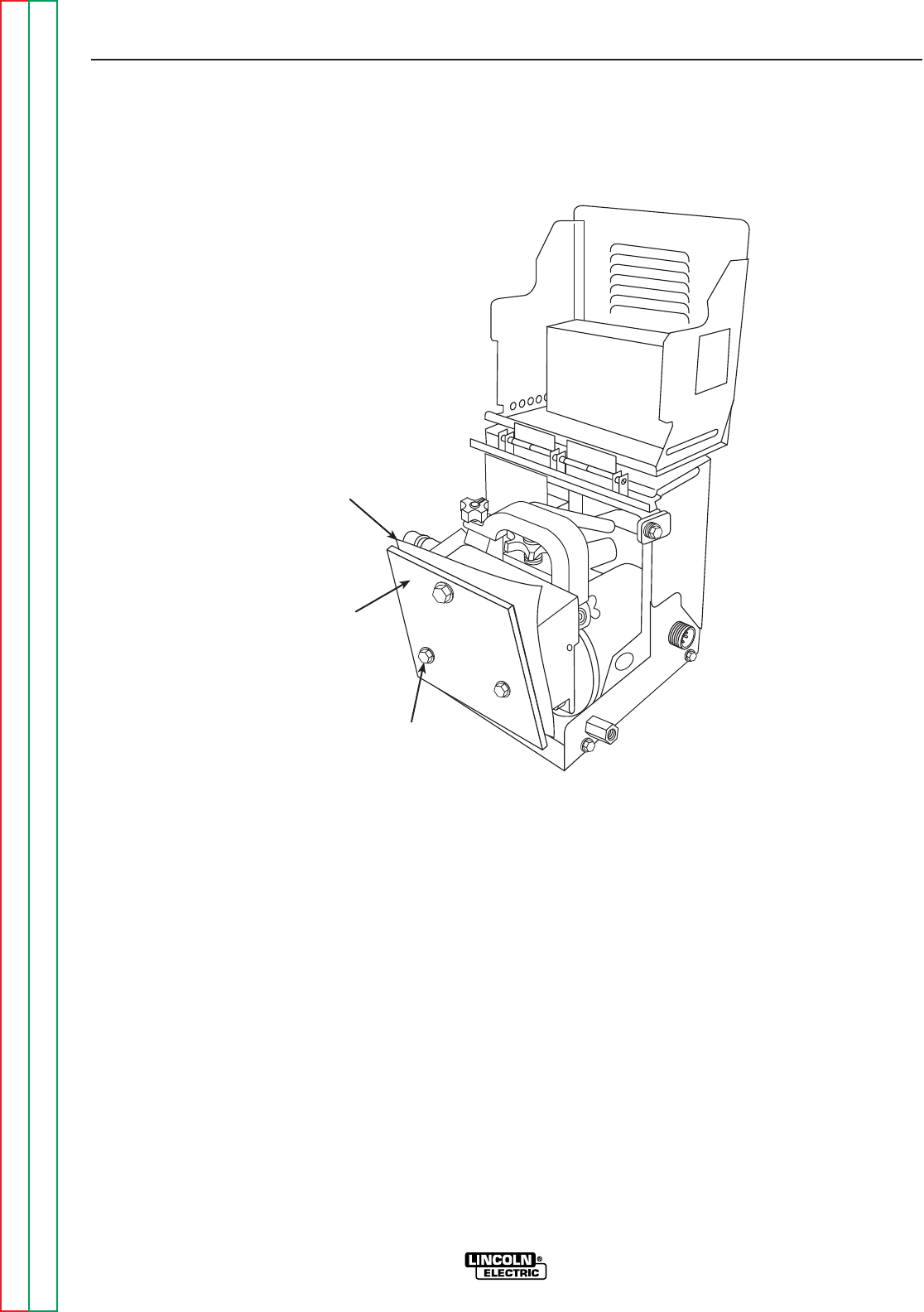
13. Using the 7/16" wrench, remove the bolts
and associated washers holding the glastic
mounting board and mylar insulator to the
gear box assembly. Remove the copper
reed switch energizer.
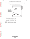
14. Using the 7/16" wrench, remove the two
bolts from the gear box inspection plate
located below the drive motor. Remove the
inspection plate. This will give access to one
of the slot head screws mounting the motor
to the gear box assembly.
See Figure F.25.
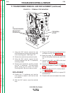
FIGURE F.24 – MOTOR AND WIRE DRIVE REMOVAL
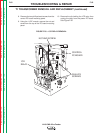
GLASTIC
MOUNTING
BOARD
MYLAR
INSULATOR
MOUNTING
BOLTS
DRIVE MOTOR REMOVAL AND REPLACEMENT (continued)