


Return to Section TOC Return to Section TOC Return to Section TOC Return to Section TOC
Return to Master TOC Return to Master TOC Return to Master TOC Return to Master TOC
TROUBLESHOOTING & REPAIR
F-35 F-35
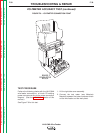
LN-9 GMA Wire Feeder
HALL EFFECT MODULE FEEDBACK
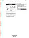
TEST PROCEDURE
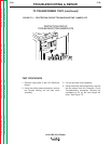
1. Remove the input power to the LN-9 GMA
wire feeder.
2. Remove any electrode wire or disengage
the drive rolls.
3.
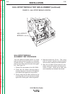
Using the phillips head screwdriver, remove
the screws from the left side cover assembly.
4. Lift the left side cover.
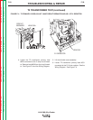
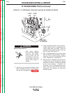
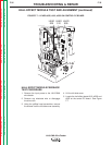
5. Locate the hall effect leads #510, #525 and
#555 on the control PC board. See Figure
F.7.
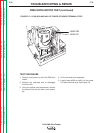
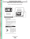
HALL EFFECT MODULE TEST AND ALIGNMENT (continued)
FIGURE F.7 – LEADS #525, #510, #555 ON CONTROL PC BOARD
LEAD
525
LEAD
510
LEAD
555