


Return to Section TOC Return to Section TOC Return to Section TOC Return to Section TOC
Return to Master TOC Return to Master TOC Return to Master TOC Return to Master TOC
TROUBLESHOOTING & REPAIR
F-11 F-11
LN-9 GMA Wire Feeder
TROUBLESHOOTING GUIDE Observe Safety Guidelines
detailed in the beginning of this manual.
CAUTION
If for any reason you do not understand the test procedures or are unable to perform the test/repairs safely, con-
tact the Lincoln Electric Service Department for electrical troubleshooting assistance before you proceed. Call
216-383-2531 or 1-800-833-9353.
PROBLEMS
(SYMPTOMS)
POSSIBLE AREAS OF
MISADJUSTMENT(S)
RECOMMENDED
COURSE OF ACTION
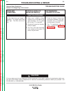
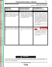
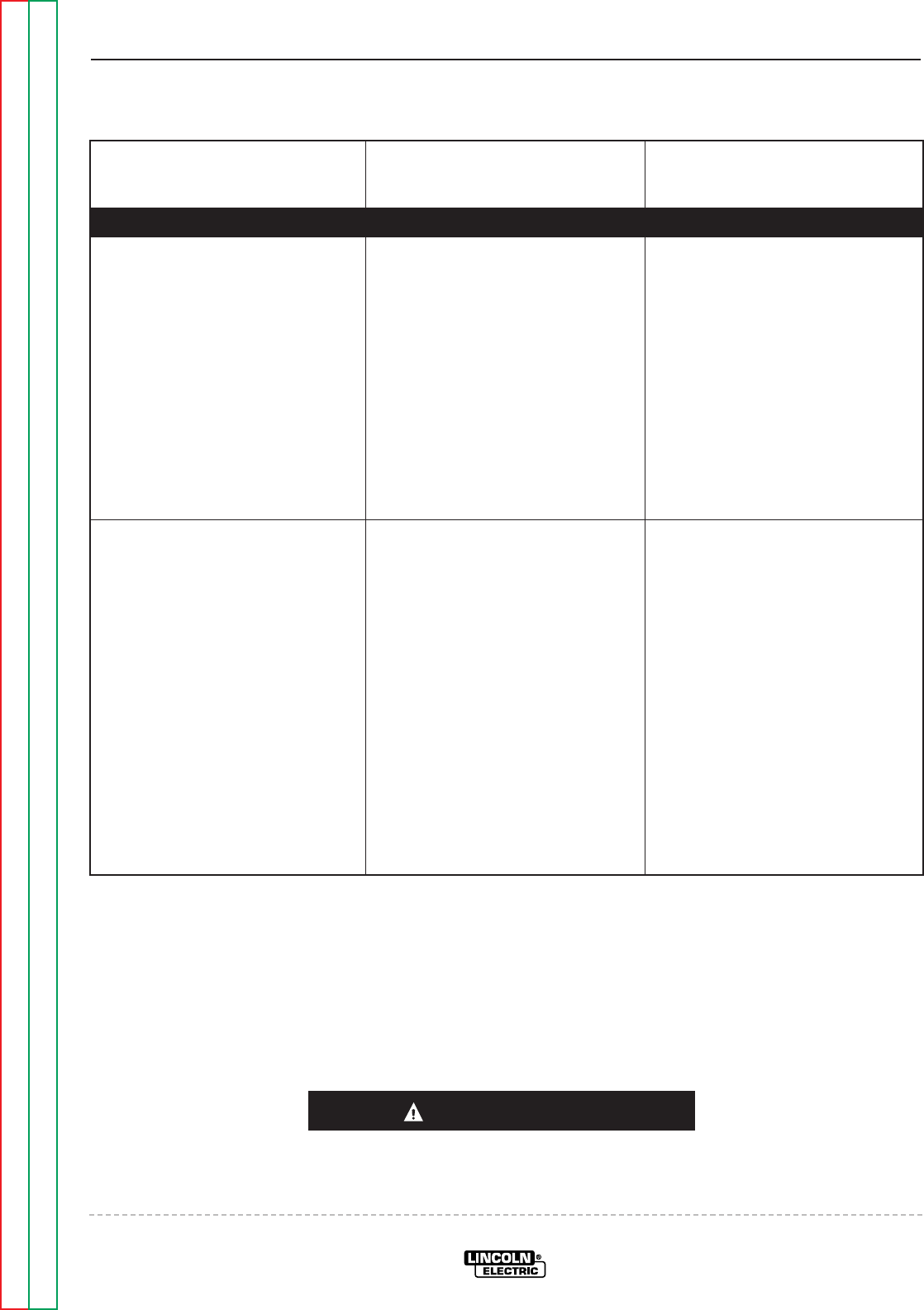
FUNCTION PROBLEMS
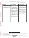
The SET voltage is erratic or not
adjustable over the entire range of
control. The actual voltage is also
erratic like the SET voltage.
1. Check for loose or faulty con-
nections on leads #634, #635,
and #636 between the voltage
control potentiometer (R3) and
the voltage PC board.
1. Remove power to the LN-9
GMA and disconnect Plug J9
from the voltage PC board.
Check the resistance of the volt-
age control potentiometer (R3).
When measured from the wiper
(lead #635) to lead #634, the
resistance should vary smoothly
from 0 to 10,000 ohms when the
shaft is rotated.
2. The voltage PC board may be
faulty. Replace.
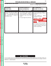
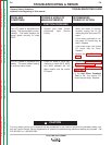
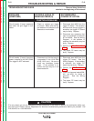
The field fuse (F101), located on
the power PC board, repeatedly
fails.
1. Make sure the replacement fuse
is a 4/10 amp slow blow type
fuse.
1. Perform the
T1 Transformer
Test.
2. Disconnect the meter PC board.
If the problem is resolved, the
meter PC board may be faulty.
3. The power PC board may be
faulty. Replace.