


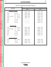
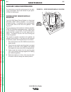
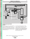
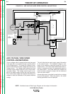
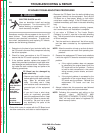

TRIGGER AND SHUTDOWN
CIRCUIT
When the gun trigger switch is activated (closed), the
trigger board completes the trigger signal path. This
energizes the CR1 relay located on the power board.
The CR1 relay activates the wire drive motor and the
#2 and #4 circuit, which then activates the Lincoln
welding power source. The CR1 relay is also used to
energize the gas solenoid.
The normally closed relay located on the voltage
board is in series with the trigger signal. If an out-of-
voltage-range signal or a ground fault condition
should occur, the CR501 (on voltage board) relay con-
tacts would "open," and the trigger signal path would
be interrupted. This would cause the wire feeder to
"shut down" until the gun trigger is released or the
ground fault protector is reset.
THEORY OF OPERATION
E-3 E-3
LN-9 GMA Wire Feeder
Return to Section TOC Return to Section TOC Return to Section TOC Return to Section TOC
Return to Master TOC Return to Master TOC Return to Master TOC Return to Master TOC
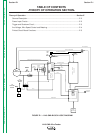
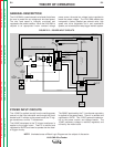
NOTE: Unshaded areas of Block Logic Diagram are the subject of discussion.
FIGURE E.3 – TRIGGER AND SHUTDOWN CIRCUIT
INPUT
CONNECTOR
TO
VOLTAGE
BOARD
TO
CONTROL
BOARD
METER
BOARD
VOLTS
SPEED
SWITCH
T1
CIRCUIT
BREAKER
R1
TRIGGER
CONNECTOR
TRIGGER
BOARD
F
U
S
E
T2
C
O
N
T
R
O
L
B
O
A
R
D
VOLTAGE
BOARD
P
O
W
E
R
B
O
A
R
D
GROUND
LEAD
PROTECTOR
WIRE
FEED
MOTOR
WIRE
SPEED
CONTROL
VOLTAGE
CONTROL
POLARITY
SWITCH
VOLTAGE SENSING
VOLTAGE CONTROL
POWER SOURCE OUTPUT TRIGGER (#2 )
S
H
U
T
D
O
W
N
+ 15VDC
+ 15VDC
WIRE SPEED CONTROL
GEAR
BOX
TRIGGER SIGNAL
TRIGGER SIGNAL
R
E
F
E
R
E
N
C
E
V
O
L
T
A
G
E
WORK
ELECTRODE VOLTAGE SENSING
24VAC
28VAC
10VAC
HALL EFFECT
DEVICE
GAS
SOLENOID