


INSTALLATION
A-11 A-11
LN-9 GMA Wire Feeder
Return to Section TOC Return to Section TOC Return to Section TOC Return to Section TOC
Return to Master TOC Return to Master TOC Return to Master TOC Return to Master TOC
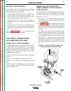
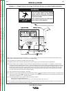
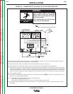
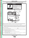
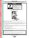
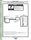
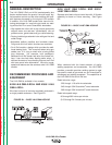
FIGURE A.8 – CONNECTION OF LN-9 GMA TO V300 POWER SOURCES
ELECTRODE CABLE
TO LN-9 GMA
TO WORK
14 PIN
AMPHENOL
INVERTEC
POWER SOURCE
WITH 110/115V AUX.
K596 REMOTE
CONTROL CABLE
ASSEMBLY
LN-9 GMA WITH
K608-1 AND
K442-1 KITS
P10,J10'
2
3
4
5
6
7
10
11
12
K608-1
CONNECTION
DETAIL
P10',J10
2
3
4
5
6
11
7
12
530A
521
500
500
524
C
3.9K ohm
B
533
N.A. Welding cable must be sized for current and duty cycle of application.
N.B. Diagram shows electrode positive. To change polarity, turn power “OFF”, reverse electrode and work cable at power source. Set
meter polarity switch on rear of invertec to coincide with polarity used. Set LN-9 GMA polarity switch also.
N.C. Install K608-1 adapter in line with P10 to LN-9 GMA voltage board and secure to adjacent harness with wire tie provided. Turn
“start” trimmer on voltage board per instructions in V300 manual.
N.D. For GMAW welding, install Pulse Power Filter Kit K442-1 in LN-9 GMA.
WARNING
• Turn off input power to the welding
power source using the disconnect
switch at the fuse box before connect-
ing the wire feeder
• Only qualified persons should install,
use or service this machine.
ELECTRIC SHOCK
can kill.