


PROCEDURE
1. Remove the input power to the V350-PRO.
2. Using a 5/16” nut driver remove the case wrap-
around cover.
3. Perform the Input Filter Capacitor Discharge
Procedure detailed earlier in this section.
Observe static precautions detailed in PC Board
Troubleshooting Procedures at the beginning of
this section. Failure to do so can result in perma-
nent damage to equipment.
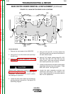
4. Locate the main switch board and all associat-
ed plug and lead connections. See figure F.23.
See Wiring Diagram.
5. Using a 5/16” and 3/8” nut driver remove the
input lead shield from the area at the bottom of
the main switch board.
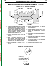
6. Using a 7/16” socket, remove leads 201, 202,
203, 204, 205, 206, 207, 208, 209 from the
switch board. Note lead terminals locations
and washer positions upon removal.
7. Locate and disconnect the three harness plugs
associated with the main switch board. Plugs
#J20, #J21, #J22. See Figure F.23.
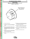
8. Locate the eight capacitor terminals and
remove the nuts using a 7/16” socket or nut
driver. Note the position of the washers behind
each nut for replacement.
CAUTION
V350-PRO
Return to Section TOC Return to Section TOC Return to Section TOC Return to Section TOC
Return to Master TOC Return to Master TOC Return to Master TOC Return to Master TOC
TROUBLESHOOTING & REPAIR
F-62 F-62
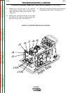
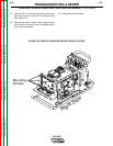
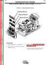
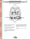
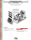
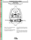
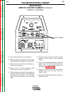
FIGURE F.23 – MAIN SWITCH BOARD LEAD LOCATIONS
MAIN SWITCH BOARD REMOVAL & REPLACEMENT (continued)
- +
- +
- + - +
208
201
209
204
205
206
203
J21
J20
J22
202
207