


Observe static precautions detailed in PC
Board Troubleshooting Procedures at the
beginning of this section.
8. The front of the machine may now gently be pulled
forward to gain access to the Control Board. Note:
The front of the machine cannot be removed com-
pletely, only pulled forward a few inches.
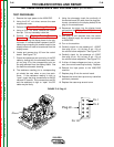
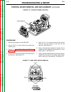
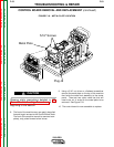
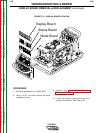
9. Using a 5/16” nut driver or a flathead screwdriver
remove the metal plate on the top of the machine
that holds the case front assembly to the center
panel. There are two nylon cable ties that will
need to be cut in order for the metal plate to be
removed. See Figure F.18.
10. The control board is now accessible to replace.
CAUTION
V350-PRO
Return to Section TOC Return to Section TOC Return to Section TOC Return to Section TOC
Return to Master TOC Return to Master TOC Return to Master TOC Return to Master TOC
TROUBLESHOOTING & REPAIR
F-53 F-53
WARN ING
REM OTE
POWE R
OFF
ON
A
AMPS
A
V
VOLTS
WELD TERMINALS
SELECT
OUTPUT
LINCOLN
ELECTRIC
INVERTEC V350-PRO
Metal Plate
5/16" Screws
Plug J8
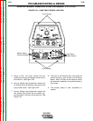
FIGURE F.18. - METAL PLATE LOCATION
CONTROL BOARD REMOVAL AND REPLACEMENT (continued)