


Return to Section TOC Return to Section TOC Return to Section TOC Return to Section TOC
Return to Master TOC Return to Master TOC Return to Master TOC Return to Master TOC
V350-PRO
TROUBLESHOOTING & REPAIR
F-58 F-58
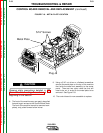
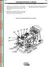
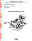
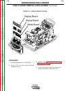
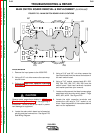
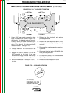
FIGURE F.21 – DISPLAY BOARD LOCATION
W
ARN ING
REM OTE
POWE R
OFF
ON
A
AMPS
A
V
VOLTS
WELD TERMINALS
SELECT
OUTPUT
LINCOLN
ELECTRIC
INVERTEC V350-PRO
L11130-1
CS71D1
Display Board
L
11
1
0
7
-2
S
T
A
T
U
S
IN
P
U
T
Status Board
L11110-1
M
ODE SELECT
Mode Board
DISPLAY BOARD REMOVAL & REPLACEMENT (continued)
PROCEDURE
1. Remove input power to the V350-PRO.
2. Using a 5/16” nut driver remove the case
wraparound cover.
3. Perform the Input Filter Capacitor
Discharge Procedure detailed earlier in this
section.
4. Locate the display board behind the front
panel of the machine. See Figure F.21.