


TROUBLESHOOTING & REPAIR
DISPLAY BOARD REMOVAL & REPLACEMENT (continued)
F-59 F-59
V350-PRO
Return to Section TOC Return to Section TOC Return to Section TOC Return to Section TOC
Return to Master TOC Return to Master TOC Return to Master TOC Return to Master TOC
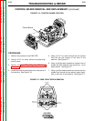
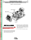
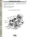
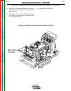
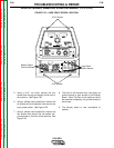
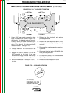
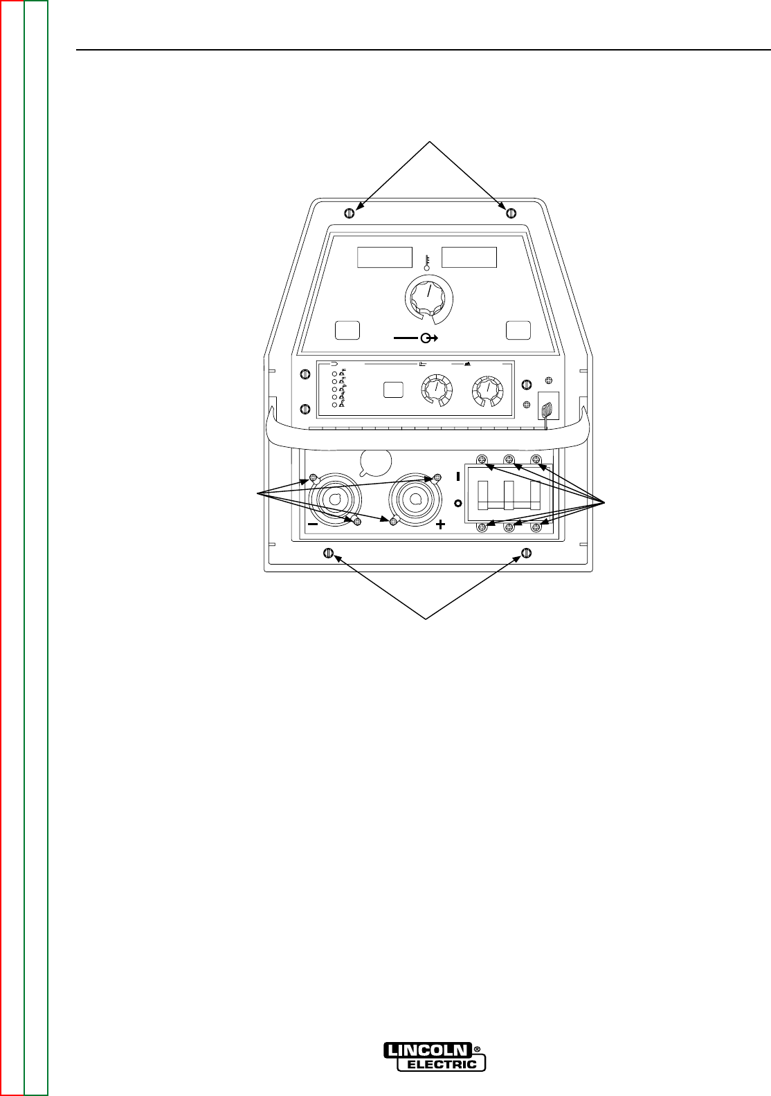
FIGURE F.22 – CASE FRONT SCREW LOCATION
Input Power
Switch Screws
Welder Output
Terminal Screws
5/16" Screws
5/16" Screws
OFF
OFF
OFF
OFF
OFF
OFF
OFF
OFF
ON
ON
HOT STAR
AR
TWELD MODE
WELD MODE
ARC CONTR
ARC CONTR
OL
OL
CC-STICK SOFT
CC-STICK SOFT
CC-STICK CRISP
CC-STICK CRISP
TIG GT
TIG GT
AW
CV
CV
-WIRE
-WIRE
CV
CV
-FLUX CORED
-FLUX CORED
-4
-4
+4
+4
+2
+2
-2
-2
0
-6
-6
+6
+6
-10
-10
SOFT
SOFT
CRISP
CRISP
+10
+10
-8
-8
+8
+8
5
4
3
2
1
0
6
10
10
9
8
7
SELECT
SELECT
REMO
REMO
TE
TE
ON
ON
REMO
REMO
TE
TE
LOCAL
LOCAL
m
WELD
WELD
TERMINALS
TERMINALS
OUTPUT
OUTPUT
CONTR
CONTR
OL
OL
SELECT
SELECT
SELECT
SELECT
MPS
MPS
A
OL
OL
TS
TS
V
5. Using a 5/16” nut driver remove the four
screws from the top and bottom of the front of
the machine. See Figure F.22.
6. Using a phillips head screwdriver remove the
six screws and their washers from around the
input power switch. See Figure F.22.
7. Using a phillips head screwdriver remove the
four screws from around the two welder out-
put terminals on the front of the machine. See
Figure F.22.
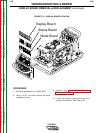
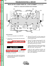
8. The front of the machine may now gently be
pulled forward to gain access to the display
Board. Note: The front of the machine cannot
be removed completely, only pulled forward a
few inches.
9. The display board is now accessible to
replace.