


TROUBLESHOOTING & REPAIR
F-68 F-68
V350-PRO
Return to Section TOC Return to Section TOC Return to Section TOC Return to Section TOC
Return to Master TOC Return to Master TOC Return to Master TOC Return to Master TOC
MODE BOARD
REMOVAL AND REPLACEMENT (continued)
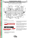
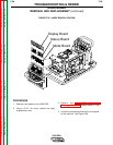
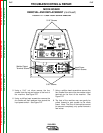
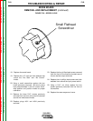
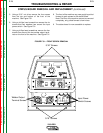
FIGURE F.28. – CASE FRONT
9. Remove plug #J34 from the mode board.
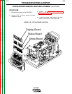
10. Remove plug #J31 originating from the status
board located directly above the mode board.
11. Open the cover of the weld mode display on
the front of the machine.
12. Using a 5/16” nut driver, remove the three
5/16” screws as shown in Figure F.28.
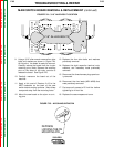
13. Carefully maneuver the the mode faceplate up
and away from the machine. The bottom of
the plate will come out first. Note: The mode
board will still be attached to its mounting
plate.
14. Place both knobs in the full counter clockwise
position to gain access to the mounting
screws.
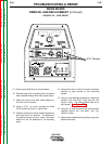
15. Using a small flathead screwdriver, loosen the
screw in the “Hot Start” knob and the “Arc
Control” knob. The knobs should slide off of
their shafts. See Figure F.29.
16. Using a 1/4” wrench remove the nuts and their
washers behind the “Hot Start” and “Arc
Control” knobs.
17. Remove the mode board by gently prying from
behind the board.
OFF
OFF
OFF
OFF
OFF
OFF
OFF
OFF
ON
ON
HO
HO
T ST
T ST
ARTWELD MODE
WELD MODE
ARC CONTR
ARC CONTR
OL
OL
CC-STICK SOFT
CC-STICK CRISP
TIG GTAW
CV-WIRE
CV-FLUX CORED
-4 +4
+4
+2
+2
-2
0
-6 +6
+6
-10
-10
SOFT
SOFT
CRISP
CRISP
+10
+10
-8
+8
+8
5
4
3
2
1
0
6
10
10
9
8
7
SELECT
REMO
REMO
TE
TE
ON
ON
REMO
REMO
TE
TE
LOCAL
LOCAL
m
WELD
WELD
TERMINALS
TERMINALS
OUTPUT
OUTPUT
CONTR
CONTR
OL
OL
SELECT
SELECT
SELECT
SELECT
MPS
MPS
A
OL
OL
TS
TS
V
5/16" Screws