


Return to Section TOC Return to Section TOC Return to Section TOC Return to Section TOC
Return to Master TOC Return to Master TOC Return to Master TOC Return to Master TOC
V350-PRO
TROUBLESHOOTING & REPAIR
F-52 F-52
PROCEDURE
1. Remove input power to the V350-PRO.
2. Using a 5/16” nut driver remove the case wrap-
around cover.
3. Perform the Input Filter Capacitor Discharge
Procedure detailed earlier in this section.
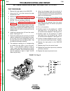
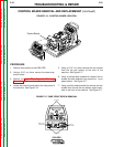
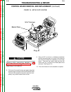
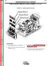
4. Locate the control board behind the front panel of
the machine. See Figure F.16.
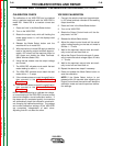
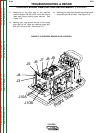
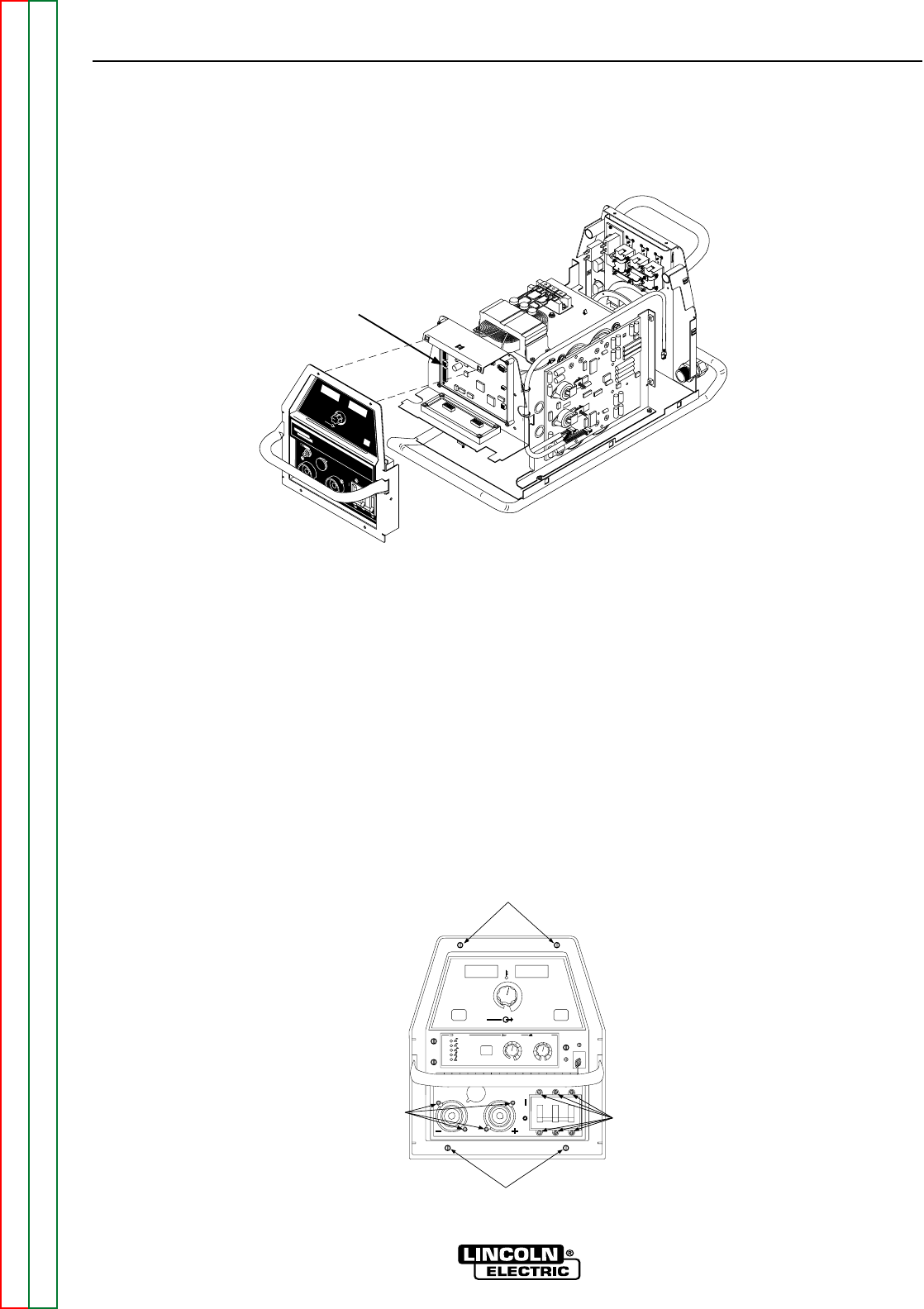
5. Using a 5/16” nut driver remove the four screws
from the top and bottom of the front of the
machine. See Figure F.17.
6. Using a phillips head screwdriver remove the six
screws and their washers from around the input
power switch. See Figure F.17.
7. Using a phillips head screwdriver remove the four
screws from around the two welder output termi-
nals on the front of the machine. See Figure F.17.
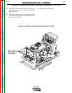
CONTROL BOARD REMOVAL AND REPLACEMENT (continued)
Input Power
Switch Screws
Welder Output
Terminal Screws
5/16" Screws
5/16" Screws
OFF
OFF
OFF
OFF
OFF
OFF
OFF
OFF
ON
ON
HO
HO
T ST
T ST
AR
AR
TWELD MODE
WELD MODE
ARC CONTR
ARC CONTR
OL
OL
CC-STICK SOFT
CC-STICK SOFT
CC-STICK CRISP
CC-STICK CRISP
TIG GT
TIG GT
AW
CV
CV
-WIRE
-WIRE
CV
CV
-FLUX CORED
-FLUX CORED
-4
-4
+4
+4
+2
+2
-2
-2
0
-6
-6
+6
+6
-10
-10
SOFT
SOFT
CRISP
CRISP
+10
+10
-8
-8
+8
+8
5
4
3
2
1
0
6
10
10
9
8
7
SELECT
SELECT
REMO
REMO
TE
TE
ON
ON
REMO
REMO
TE
TE
LOCAL
LOCAL
m
WELD
WELD
TERMINALS
TERMINALS
OUTPUT
OUTPUT
CONTR
CONTR
OL
OL
SELECT
SELECT
SELECT
SELECT
MPS
MPS
A
OL
OL
TS
TS
V
FIGURE F.16 - CONTROL BOARD LOCATION
FIGURE F.17 CASE FRONT SCREW REMOVAL
WARNI NG
REMOT E
POW
ER
OFF
ON
A
AMPS
A
V
VOLTS
W
E
LD
TE
R
M
IN
ALS
S
E
LEC
T
OUTPUT
LINCOLN
ELECTRIC
INVERTEC V350-PRO
Control Board