


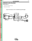
CONNECTION OF LINCOLN ELEC-
TRIC WIRE FEEDERS
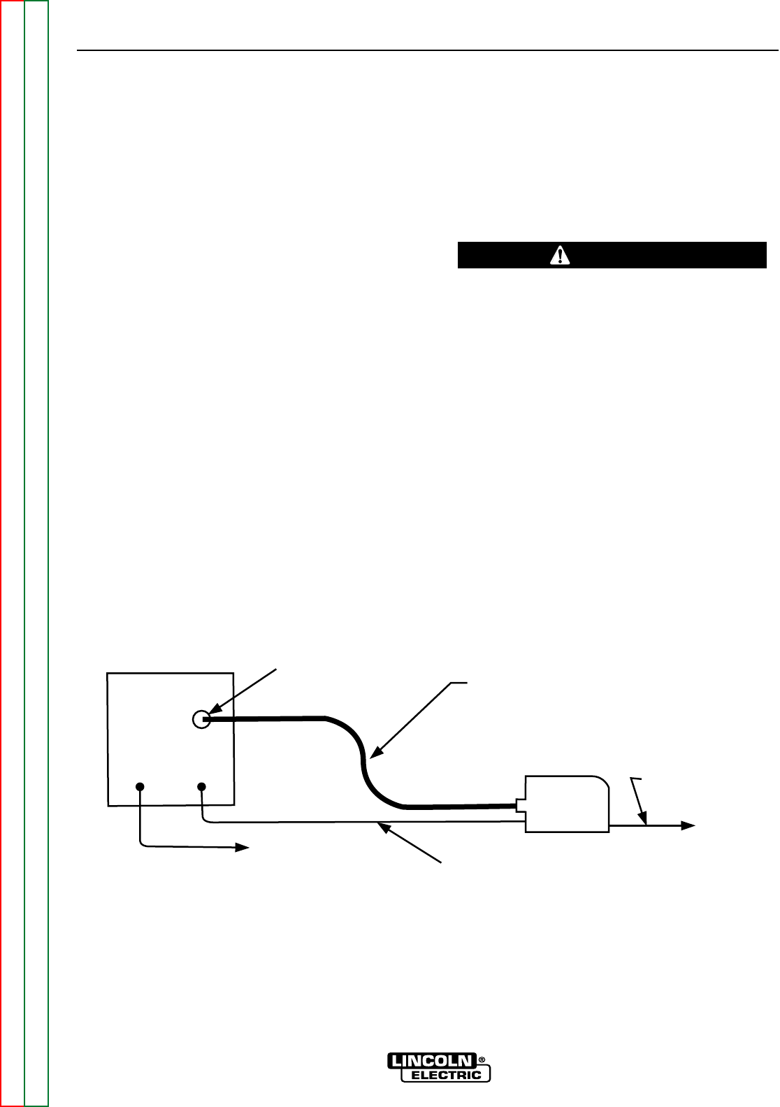
CONNECTION OF THE LN-25 TO THE
V350-PRO “ACROSS THE ARC” WITH
OPTIONAL 6 PIN K441-1 REMOTE CON-
TROL.
1. Remove input power to the V350-PRO.
2. Connect the electrode cable to the output terminal
of polarity required by the electrode. Connect the
work lead to the other terminal. Welding cable
must be sized for current and duty cycle of the
application.
3. Attach the single lead from the LN-25 control box
to the work using the spring clip on the end of the
lead. This is only a control lead - it carries no
welding current.
4. Set the voltmeter switch to the electrode polarity
chosen.
5. Set “CONTROL SELECT” to “REMOTE”.
6. Set the “MODE” to the “CV-WIRE” position.
7. Set “WELD TERMINALS SELECT” to the “ON”
position.
If you are using an LN-25 without an internal con-
tactor, the electrode will be “HOT” when the V350-
PRO is energized.
8. Set the “ARC CONTROL” to the “O” position and
then adjust to suit.
CAUTION
ACCESSORIES
C-2 C-2
V350-PRO
Return to Section TOC Return to Section TOC Return to Section TOC Return to Section TOC
Return to Master TOC Return to Master TOC Return to Master TOC Return to Master TOC
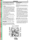
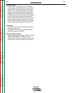
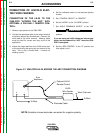
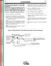
+ -
6 pin
Amphenol
To Work
Electrode Cable
Optional K444-1
Remote Control
LN-25
Wire Feeder
Work Clip Lead
To Work
Figure C.1 V350-PRO/LN-25 ACROSS THE ARC CONNECTION DIAGRAM
NOTE: Illustation shows electrode connected for negative polarity.