


F-55 F-55
V350-PRO
Return to Section TOC Return to Section TOC Return to Section TOC Return to Section TOC
Return to Master TOC Return to Master TOC Return to Master TOC Return to Master TOC
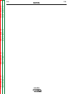
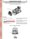
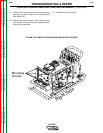
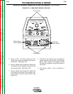
14. Using a 3/8” nut driver remove the four mounting
nuts from the four corners of the control board.
See Figure F.20.
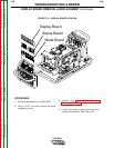
15. Remove the control board. Note: Gentle prying
from behind the board using a flathead screw-
driver may be required.
16. Replace the control board.
TROUBLESHOOTING & REPAIR
CONTROL BOARD REMOVAL AND REPLACEMENT (continued)
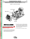
FIGURE F.20 CONTROL BOARD MOUNTING SCREW LOCATION
Right Side
Mounting
Screws