


Section E-1 Section E-1
V350-PRO
Theory of Operation .............................................................................................................Section E
General Description ....................................................................................................................E-2
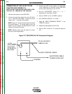
Input Line Voltage, Auxiliary Transformer and Precharge...........................................................E-2
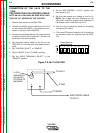
Switch Board and Main Transformer..........................................................................................E-3
Power board, Control Board, and SPI Communications............................................................E-4
Output Rectifier and Choke ........................................................................................................E-5
Thermal Protection .....................................................................................................................E-6
Protection Circuits ......................................................................................................................E-6
Over current Protection ........................................................................................................E-6
Under/Over Voltage Protection ............................................................................................E-6
Insulated Gate Bipolar Transistor (IGBT) Operation ...................................................................E-7
Pulse Width Modulation..............................................................................................................E-8
Minimum/Maximum Output..................................................................................................E-8
TABLE OF CONTENTS
-THEORY OF OPERATION SECTION-
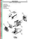
Remote
Board
Mode
Panel
Status
Panel
Display
Panel
Control Board
Choke
Positive
Output
Terminal
Negative
Output
Terminal
To Control
Board
Current
Feedback
Reconnect
Switch
Output Voltage Sense
Input switch
& 100A Breaker
Input
Rectifier
Auxiliary
Transformer
Fan
Power
Board
14 Pin
Amphenol
6 Pin
Amphenol
Remote Control & Trigger
Solenoid Supply
40VDC
RS232 Supply +5VDC
SPI Supply +15VDC +5VDC
Machine Control Supply
+15VDC, -15VDC, +6VDC
40VDC
28VAC
24VAC
115VAC, 42VAC
Main Switch Board
115VAC Fan Supply
Optional Solenoid
SPI Communications & +15VDC, +5VDC Supply
Fan Control
V/F Capacitor Feedback (2)
Soft Start Control
Input Relay Control
Primary Current Feedback
IGBT Drive Signal
Primary
Current
Sensor
Primary
Current
Sensor
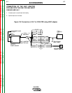
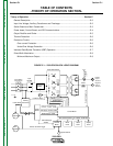
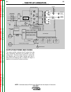
FIGURE E.1 – V350-PRO BLOCK LOGIC DIAGRAM
Return to Master TOC Return to Master TOC Return to Master TOC Return to Master TOC