


Return to Section TOC Return to Section TOC Return to Section TOC Return to Section TOC
Return to Master TOC Return to Master TOC Return to Master TOC Return to Master TOC
TROUBLESHOOTING & REPAIR
F-34 F-34
V350-PRO
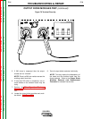
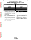
AUXILIARY TRANSFORMER TEST (continued)
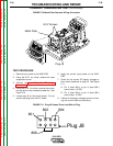
TEST PROCEDURE
1. Remove input power to the V350-PRO.
2. Using a 5/16” nut driver, remove the case
wraparound cover.
3. Perform the Input Capacitor Discharge
Procedure detailed earlier in this section.
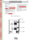
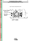
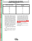
4. Locate the auxiliary transformer. See Figure
F.8.
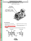
5. Locate the secondary leads and plugs P52
and P56. See Figure F.8 and F.9.
FIGURE F.8 Auxiliary Transformer
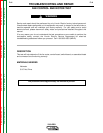
FIGURE F.9 Plug Lead Connections Viewed From Transformer Lead Side of Plug
W
A
R
N
IN
G
R
E
M
O
TE
P
O
W
E
R
O
F
F
O
N
A
A
M
P
S
A
V
V
O
L
T
S
W
ELD TERMINALS
SELECT
O
U
T
P
U
T
LINCOLN
ELECTRIC
INVERTEC V350-PRO
Auxiliary
Transformer
Secondary Lead
Plugs P52 and P56
LEAD
541
LEAD
31
LEAD
24
LEAD
42
LEAD
532
PLUG P52
LEAD
41A
LEAD
54
PLUG P56