


TEST PROCEDURE
1. Remove input power to the V350-PRO
machine.
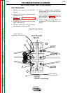
2. Using a 5/16” nut driver, remove the case
wraparound cover.
3. Perform the Capacitor Discharge
Procedure detailed earlier in this section.
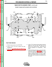
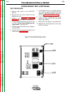
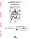
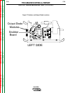
4. Locate the power board and plugs J41, J42
and J43. Do not remove plugs from the
power board. See Figure F.4.
5. Carefully apply the correct input voltage to
the V350-PRO.
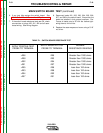
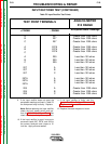
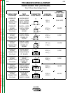
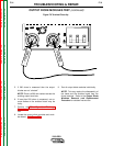
6. Carefully test for the correct voltages at the
power board. See Table F.3.
7. If the 40VDC is low, or not present at plug
J41, check the rectifier bridge and C5 filter
capacitor. See Wiring Diagram. Also per-
form the Auxiliary Transformer Test.
8. If any of the DC voltages are low, or not
present at plugs J42 or J43, the power
board may be faulty.
9. Remove the input power to the V350-PRO.
10. Replace the case wraparound cover using
a 5/16” nut driver.
TROUBLESHOOTING & REPAIR
F-26 F-26
V350-PRO
Return to Section TOC Return to Section TOC Return to Section TOC Return to Section TOC
Return to Master TOC Return to Master TOC Return to Master TOC Return to Master TOC
POWER BOARD TEST (CONTINUED)
J42
J41
J43
Figure F.4 Power Board Plug Location