


V350-PRO
Return to Section TOC Return to Section TOC Return to Section TOC Return to Section TOC
Return to Master TOC Return to Master TOC Return to Master TOC Return to Master TOC
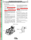
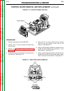
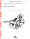
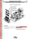
11.. Beginning at the right side of the machine
remove plugs J10A and J10B. Note: Be sure to
label each plugs position upon removal. See
Figure F.19.
12. Working your way across the top of the board
from right to left, label and remove plugs #J9,
#J8, #J7, #J6, and #J5. See Figure F.19.
13. Working your way down the left side of the board,
remove plugs #J4 and #J3. See Figure F.19.
TROUBLESHOOTING & REPAIR
CONTROL BOARD REMOVAL AND REPLACEMENT (continued)
F-54 F-54
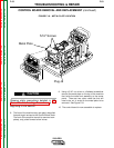
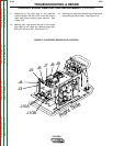
FIGURE F.19 CONTROL BOARD PLUG LOCATION
Right Side
J10B
J10A
J9
J8
J7
J6
J5
J4
J3