


SWITCH BOARD &
MAIN TRANSFORMER
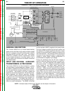
There is one switch board in the Invertec V350-Pro.
This board incorporates two pairs of input capacitors,
two insulated gate bipolar transistor (IGBT) switching
circuits, a fan motor drive circuit, and a voltage/fre-
quency capacitor feedback circuit. The two capaci-
tors in a pair are always in series with each other.
When the reconnect switch is in the lower voltage
position the capacitor pairs are in parallel . Thus two
series capacitors in parallel with two series capacitors.
When the reconnect switch is in the high voltage posi-
tion the two capacitor pairs are in series. Thus four
capacitors in series. This is required to accommodate
the higher input voltages.
When the input capacitors are fully charged they act
as power supplies for the IGBT switching circuits.
When welding output is required the Insulated Gate
Bipolar Transistors switch the DC power from the input
capacitors, "on and off" thus supplying a pulsed DC
current to the main transformer primary windings. See
IGBT Operation Discussion and Diagrams in this
section. Each IGBT switching circuit feeds current to
a separate, oppositely wound primary winding in the
main transformer. The reverse directions of current
flow through the main transformer primaries and the
offset timing of the IGBT switching circuits induce an
AC square wave output signal at the secondary of the
main transformer. The two current transformers (CT)
located on the switch board monitor these primary
currents. If the primary currents become abnormally
high the control board will shut off the IGBTs, thus dis-
abling the machine output. The DC current flow
through each primary winding is clamped back to
each respective input capacitor when the IGBTs are
turned off. This is needed due to the inductance of the
transformer primary winding. The firing of the two
switch boards occurs during halves of a 50 microsec-
ond interval, creating a constant 20 KHZ output. In
some low open circuit Tig modes the firing frequency
is reduced to 5KHZ.
The Invertec V350-Pro has a F.A.N. fan as needed cir-
cuit. The fan operates when the welding output ter-
minals are energized or when a thermal over tempera-
ture condition exists. Once the fan is activated it will
remain on for a minimum of five minutes. The fan dri-
ver circuit is housed on the switch board but it is acti-
vated from a control board signal.
THEORY OF OPERATION
E-3 E-3
V350-PRO
Return to Section TOC Return to Section TOC Return to Section TOC Return to Section TOC
Return to Master TOC Return to Master TOC Return to Master TOC Return to Master TOC
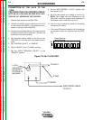
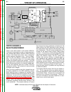
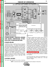
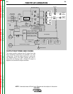
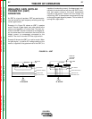
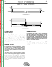
NOTE: Unshaded areas of Block Logic Diagram are the subject of discussion.
FIGURE E.3 – SWITCH BOARD & MAIN TRANSFORMER
Remote
Board
Mode
Panel
Status
Panel
Display
Panel
Control Board
Choke
Positive
Output
Terminal
Negative
Output
Terminal
To Control
Board
Current
Feedback
Reconnect
Switch
Output Voltage Sense
Input switch
& 100A Breaker
Input
Rectifier
Auxiliary
Transformer
Fan
Power
Board
14 Pin
Amphenol
6 Pin
Amphenol
Remote Control & Trigger
Solenoid Supply
40VDC
RS232 Supply +5VDC
SPI Supply +15VDC +5VDC
Machine Control Supply
+15VDC, -15VDC, +6VDC
40VDC
28VAC
24VAC
115VAC, 42VAC
Main Switch Board
115VAC Fan Supply
Optional Solenoid
SPI Communications & +15VDC, +5VDC Supply
Fan Control
V/F Capacitor Feedback (2)
Soft Start Control
Input Relay Control
Primary Current Feedback
IGBT Drive Signal
Primary
Current
Sensor
Primary
Current
Sensor