


TROUBLESHOOTING AND REPAIR
SPI CABLE RESISTANCE AND VOLTAGE TEST (continued)
F-46 F-46
V350-PRO
Return to Section TOC Return to Section TOC Return to Section TOC Return to Section TOC
Return to Master TOC Return to Master TOC Return to Master TOC Return to Master TOC
TEST PROCEDURE
1. Remove the input power to the V350-PRO.
2. Using the 5/16” nut driver, remove the case
wraparound cover.
3. Perform the Capacitor Discharge Procedure.
4. Using a 5/16” nut driver, remove the control
box top. Cut any necessary cable ties.
5. Perform the Display Board Removal
Procedure. Do not remove the SPI ribbon
cable connecting the display board to the sta-
tus board. If a remote board is present, the SPI
cable plug connecting the remote board to the
display board will have to be removed from the
display board.
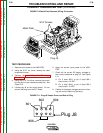
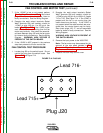
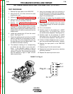
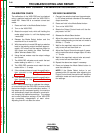
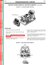
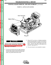
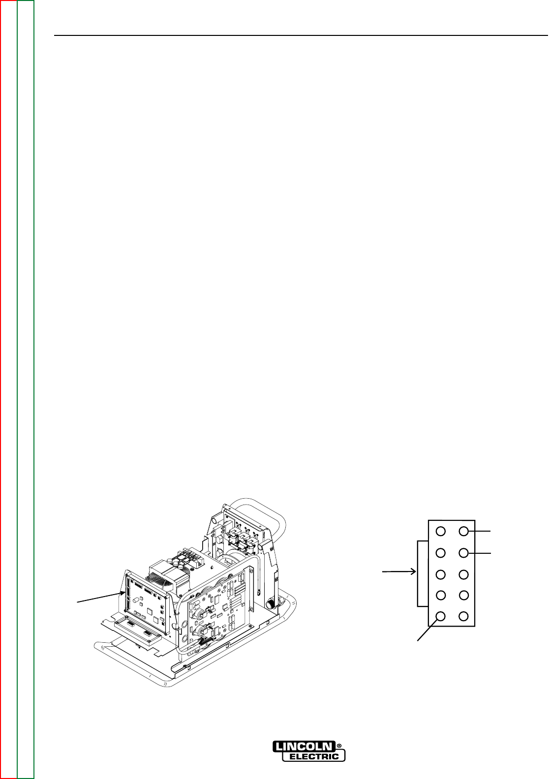
6. Locate and remove plug J3 from the control
board. See Figure F.15.
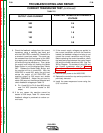
7. Check the resistance and continuity of the SPI
cable by testing with the ohmmeter from each
pin on plug J3 to the corresponding pins on
the plug removed from the display board. See
the machine schematic drawing.
8. The resistance reading pin to corresponding
pin should be zero ohms or very low resis-
tance. If the resistance reading is high or
“open” check the plug connections to the SPI
network PC boards. If the connections are OK
and the resistance is high or “open” the SPI
cable may be faulty.
9. Using the ohmmeter check the continuity of
the remote board SPI cable from the plug (pre-
viously connected to the display board) to the
plug on the remote board.
10. Reconnect the plugs into the display board
and perform the Display Board Replacement
Procedure.
11. With plug J3 still removed from the control
board, carefully apply the correct input power
to V350-PRO.
12. Turn on the machine.
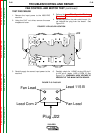
13. Carefully check for the presence of +15VDC
from plug J3 pin -1(+) to plug J3 pin -10(-) at
the control board receptacle. See Figure F.15.
14. Carefully check for the presence of +5VDC
from plug J3 pin -2(+) to plug J3 pin -10(-) at
the control board receptacle. See Figure F.15.
15. If either of these voltages are low or not pre-
sent, the control board may be faulty. Replace.
16. Remove the input power to the V350-PRO
machine.
17. Replace plug J3 into the control board.
18. Replace the control box top and any cable ties
previously removed.
19. Replace the case wrap-around cover.
Plug J3
Pin 10
Pin 1
Pin 2
FIGURE F.15 Plug J3
Right Side
J3