


TROUBLESHOOTING & REPAIR
F-69 F-69
V350-PRO
Return to Section TOC Return to Section TOC Return to Section TOC Return to Section TOC
Return to Master TOC Return to Master TOC Return to Master TOC Return to Master TOC
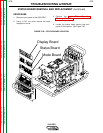
MODE BOARD
REMOVAL AND REPLACEMENT (continued)
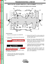
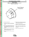
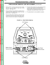
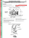
FIGURE F.29 – SCREW IN CAP
Small Flathead
Screwdriver
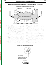
18. Replace the mode board.
19. Replace the 1/4” nuts and their washers that
mount the “Hot Start” and “Arc Control”
knobs.
20. Using a small screwdriver replace the two
knobs previously removed. Be sure to place
both potentiometers in the full counter clock-
wise position and position knobs for proper
calibration.
21. Replace the three 5/16” screws previously
removed from the front of the machine located
around the mode board knobs.
22. Replace plugs #J31 and #J34 previously
removed.
23. Replace the four phillips head screws removed
from the front of the machine located around
the two welder output terminals.
24. Replace the six phillips head screws and their
washers from around the input power switch.
25. Using a 5/16” nut driver replace the four
screws previously removed from the front of
the machine
26. Replace the case wraparound cover.