


TROUBLESHOOTING AND REPAIR
CURRENT TRANSDUCER TEST (continued)
F-38 F-38
V350-PRO
Return to Section TOC Return to Section TOC Return to Section TOC Return to Section TOC
Return to Master TOC Return to Master TOC Return to Master TOC Return to Master TOC
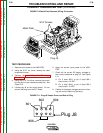
TEST PROCEDURE
1. Remove input power to the V350-PRO.
2. Using the 5/16” nut driver, remove the case
wraparound cover.
3. Perform the Input Capacitor Discharge
Procedure.
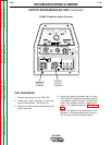
4. Using the 5/16” nut driver, remove the control
box top and cut any necessary cable ties. See
Figure F.10.
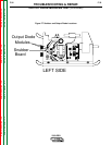
5. Locate plug J8 on the control board. Do not
remove the plug from the P.C. Board.
6. Apply the correct input power to the V350-
PRO.
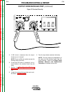
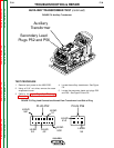
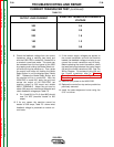
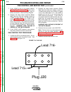
7. Check for the correct DC supply voltages to
the current transducer at plug J8. See Figure
F.11.
A. Pin 2 (lead 802+) to pin 6 (lead 806-)
should read +15 VDC.
B. Pin 4 (lead 804+) to pin 6 (lead 806-)
should read -15 VDC.
8. If either of the supply voltages are low or miss-
ing, the control board may be faulty.
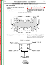
FIGURE F.10 Metal Plate Removal & Plug J8 Location
802
801
804
806
Plug J8
FIGURE F.11. Plug J8 Viewed From Lead Side of Plug
W
A
R
N
IN
G
R
E
M
O
T
E
P
O
W
E
R
O
F
F
O
N
A
A
M
P
S
A
V
V
O
L
T
S
W
ELD TERMINALS
SELECT
O
U
T
P
U
T
LINCOLN
ELECTRIC
INVERTEC V350-PRO
Metal Plate
5/16" Screws
Plug J8