


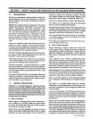

3-1.
VOLT-AMPERE
CURVES
(Chart
3-1)
3-3.
DESCRIPTION
(~3*
RATED
OUTPUT
The
volt-ampere
curves
show
the
voltage
and
amper
age
output
capabilities
of
the
unit.
Voltage
and
amper
age
adjustment
is
provided
by
the
FINE
TUNING
WIRE
SPEED
control.
Curves
of
other
setting
fall
between
the
curves
shown.
With
the
use
of
the
volt-ampere
curves,
it
is
possible
to
determine
the
weld
amperage
at
any
particular
load
volt-
age.
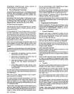
3-2.
DUTY
CYCLE
(Chart
3-2)
The
duty
cycle
is
the
percentage
of
a
ten
minute
period
that
a
welding
power
source
can
be
operated
at
a
given
output
without
overheating
and
damaging
the
unit.
This
welding
power
source
is
rated
at
60
percent
duty
cycle
when
operated
at
150
amperes.
The
unit
can
be
oper
ated
at
150
amperes
for
six
consecutive
minutes,
but
it
must
operate
at
no
load
for
the
remaining
four
minutes
to
allow
proper
cooling.
If
the
welding
amperes
decrease,
the
duty
cycle
increases.
Refer
to
the
Duty
Cycle
chart
(Chart
3-2)
to
determine
the
output
of
the
welding
power
source
at
various
duty
cycles.
a
CAUTION:
EXCEEDING
DUTY
CYCLE
RATINGS
will
damage
the
welding
power
source.
Do
not
exceed
indicated
duty
cycles.
This
unit
is
a
single-phase
constant
voltage
dc
arc
weld
ing
power
source
and
wire
feeder
system.
This
unit
is
de
signed
for
Gas
Metal
Arc
Welding
(GMAW)
with
short
circuit
or
spray
transfer.
It
is
designed
primarily
for
use
as
a
dc
Electrode
Positive/Reverse
Polarity
machine.
Rated
weld
output
is
150
amperes,
23
volts
dc,
at
60%
duty
cycle.
Models
with
the
optional
SPOT/PULSE
WELD
PANEL
provide
the
controls
for
regulating
spot
weld
time/pulse
on
time,
burnback
time,
and
pulse
off
time.
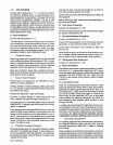
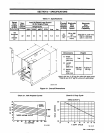
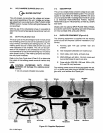
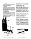
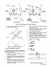
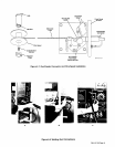
3-4.
SUPPLIED
EQUIPMENT
(Figure
3-2)
The
following
equipment
is
supplied
with
the
welding
power
source
and
requires
customer
installation
or
as
sembly:
A.
Running
gear
with
gas
cylinder
rack
and
bracket.
B.
Wall
receptacle
(200/230
volt
models
only).
C.
Work
cable,
work
clamp,
and
jack
plug.
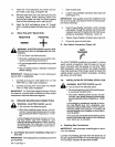
D.
MWG-200
gun
with
5/8
in.
(16
mm)
nozzle
and
two
contact
tubes
for
each
wire
size.
E.
Drive
rolls
for
.023/.025,
.030,
and
.035
in.
(0.6,
0.8,
and
0.9
mm)
hard
wire.
The
welding
power
source
is
factory
equipped
with
9
ft.
(2.7
m)
power
cord
(with
plug
on
200/230
volt
models),
gas
valve,
and
facilities
for
a
Spool
gun.
Spreader
Bar
Figure
3-2.
Supplied
Equipment
Wall
Bracket
Receptacle
OM-113
336
Page
8