


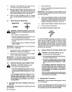
OPTIONAL
Weld
Cable
SECTION
5
OPERATOR
CONTROLS
Fine
Tuning
Wire
Speed
Control
Gun
Trigger
Power
Switch
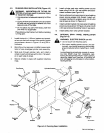
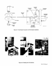
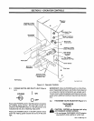
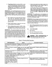
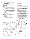
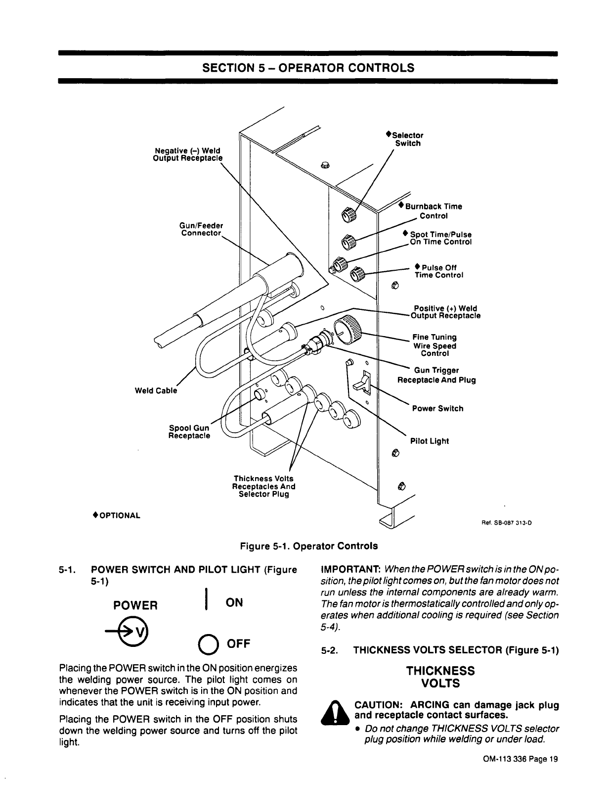
Figure
5-1.
Operator
Controls
5-1.
POWER
SWITCH
AND
PILOT
LIGHT
(Figure
5-1)
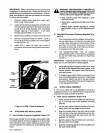
POWER
e
00FF
Placing
the
POWER
switch
in
the
ON
position
energizes
the
welding
power
source.
The
pilot
light
comes
on
whenever
the
POWER
switch
is
in
the
ON
position
and
indicates
that
the
unit
is
receiving
input
power.
Placing
the
POWER
switch
in
the
OFF
position
shuts
down
the
welding
power
source
and
turns
off
the
pilot
light.
IMPORTANT:
When
the
POWER
switch
is
in
the
ON
po
sition,
the
pilot
light
comes
on,
but
the
fan
motor
does
not
run
unless
the
internal
components
are
already
warm.
The
fan
motor
is
thermostatically
controlled
and
only
op
erates
when
additional
cooling
is
required
(see
Section
5-4).
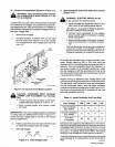
5-2.
THICKNESS
VOLTS
SELECTOR
(Figure
5-1)
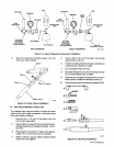
THICKNESS
VOLTS
a
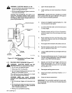
CAUTION:
ARCING
can
damage
jack
plug
and
receptacle
contact
surfaces.
Do
not
change
THICKNESS
VOLTS
selector
plug
position
while
welding
or
under
load.
Selector
Switch
Pulse
Off
Time
Control
Positive
(+)
Weld
Receptacle
Spool
Gun
Receptacle
Pilot
Light
Thickness
Volts
Receptacles
And
Selector
Plug
Ref.
SB.087
313.D
ON
OM-113
336
Page
19