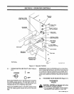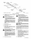
7-5.
INSPECTING
AND
REPLACING
MOTOR
BRUSHES
(Figure
7-1)
WARNING:
ELECTRIC
SHOCK
can
kill.
Do
not
touch
live
electrical
parts.
Shutdown
welding
powersource,
and
discon
nect
input
power
employing
lockout/tagging
procedures
before
inspecting,
maintaining,
or
servicing.
Lockout/tagging
procedures
Consist
of
removing
input
power
plug
from
receptacle,
padlocking
line
disconnect
switch
in
open
position,
remov
ing
fuses
from
fuse
box,
or
shutting
off
and
red-
tagging
circuit
breaker
or
other
disconnecting
device.
1.
Open
access
door.
2.
Remove
the
brush
caps
(two).
3.
Remove
brushes.
4.
Examine
brushes.
Replace
brushes
if
they
are
chipped
or
broken
or
if
less
than
1/4
in.
(6
mm)
of
brush
material
remains.
5.
Install
brushes,
and
secure
with
caps.
a
CAUTION:
DISASSEMBLY
OF
THE
MOTOR
FIELD
MAGNETS
can
result
in
personal
in
jury
and
equipment
damage.
Limit
drive
motor
repairs
to
brush
replace
ment.
The
field
magnets
are
very
strong.
If
disassem
bly
is
attempted,
injury
to
fingers
and
hands
may
result
from
the
rotor
being
drawn
back
into
the
motor.
The
field
magnets
are
matched
sets,
and
operation
may
be
affected
if
the
magnets
are
tampered
with.
Warranty
is
void
if
the
motor
is
tampered
with.
6.
Close
and
secure
access
door.
7-6.
OVERLOAD
PROTECTION
WARNING:
ELECTRIC
SHOCK
can
kill.
.
Do
not
touch
live
electrical
parts.
Shutdown
welding
powersource,
and
discon
nect
input
power
employing
lockout/tagging
procedures
before
inspecting,
maintaining,
or
servicing.
Lockout/tagging
procedures
consist
of
removing
input
power
plug
from
receptacle,
padlocking
line
disconnect
switch
in
open
position,
remov
ing
fuses
from
fuse
box,
or
shutting
off
and
red-
tagging
circuit
breaker
or
other
disconnecting
device.
A.
Circuit
Breaker
CB1
a
WARNING:
Read
and
follow
safety
informa
tion
at
beginning
of
entire
Section
7-6
before
proceeding.
The
drive
motor
is
protected
from
damage
due
to
over
load
by
circuit
breaker
CB1,
located
under
the
access
door.
Should
an
overload
on
CB1
occur,
the
contactorW
coil
would
open
thereby
stopping
all
output
from
the
welding
power
source.
If
CB1
opens,
manually
reset
the
circuit
breaker
as
fol
lows:
1.
Open
access
door.
2.
Check
for
jammed
wire
or
clogged
gun
liner,
and
correct
problem.
If
motor
overload
occurs
repeat
edly,
repair
or
replace
the
motor
or
liner.
3.
Check
for
binding
drive
gear
or
misaligned
drive
rolls,
and
correct
problem.
4.
Reset
circuit
breaker
CB1
(depress
button);
it
may
be
necessary
to
allow
a
cooling
period
before
the
breaker
can
be
reset.
5.
Close
and
secure
access
door.
6.
Resume
operation.
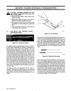
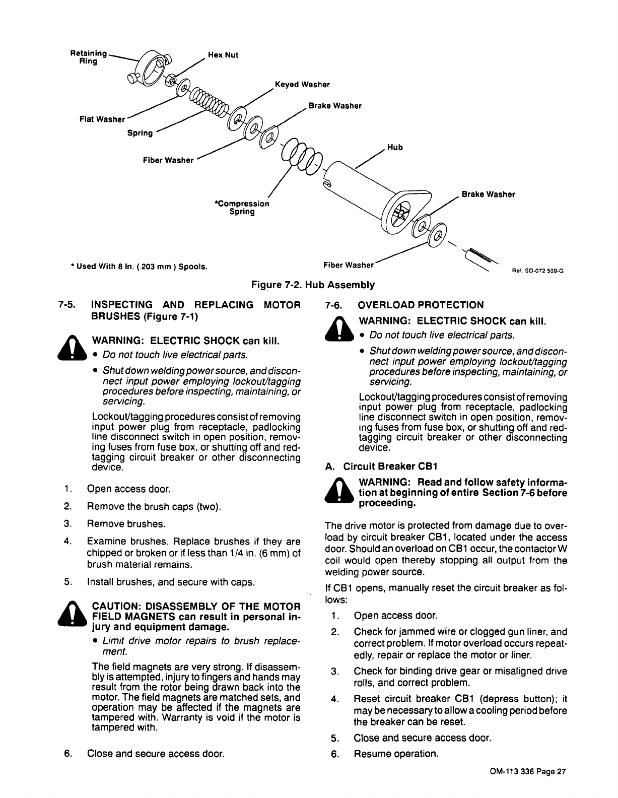
Hex
Nut
Keyed
Washer
Washer
Fiber
Washer
Retaining
Ring
Spring
*COmpreSsion
Spring
*
Used
With
8
In.
(203
mm)
Spools.
Hub
Brake
Washer
Fiber
Washer
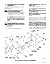
Figure
7-2.
Hub
Assembly
Pef.
SD.072
509G
OM-113
336
Page
27


