


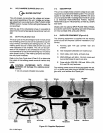
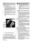

B.
Weld
Cable
Connections
Insert
Spool
Gun
welding
cable
plug
into
POSITIVE
(+)
weld
output
receptacle
with
flat
side
facing
the
recep
tacle
key.
Rotate
plug
clockwise
1/4
turn.
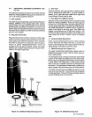
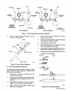
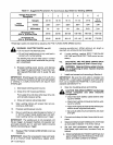
C.
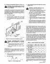
SPOOL
GUN
Receptacle
Connection
(Figure
4-9)
SPOOL
GUN
A
3-socket
SPOOL
GUN
receptacle
RC3
is
provided
for
making
connections
between
the
welding
power
source
and
the
Spool
Gun.
To
connect
the
gun,
align
keyway,
insert
gun
plug
into
receptacle,
and
rotate
threaded
col
lar
fully
clockwise.
When
gun
switch
is
closed,
the
con
tactor
energizes,
shielding
gas
flows,
and
wire
feeds.
Figure
4-9.
Front
View
Of
3-Socket
Spool
Gun
Receptacle
With
Socket
Locations
The
sockets
on
the
SPOOL
GUN
receptacle
are
desig
nated
as
follows:
Socket
A:
+24
volts
ac,
60
Hz.
Socket
B:
Welding
power
source
contactor
control;
+24
volts
closes
contactor;
0
volts
opens
contactor.
Socket
C:
+24
volts
ac,
60
Hz.
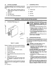
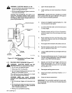
4-10.
WELDING
WIRE
SPOOL
INSTALLATION
(Figure
4-7)
J~
WARNING:
ELECTRIC
SHOCK
can
kill.
______
Do
not
touch
live
electrical
parts.
Shut
down
welding
power
source,
and
dis
connect
input
power
employing
lockout/tag
ging
procedures
before
inspecting
or
install
ing.
Lockout/tagging
procedures
consist
of
remov
ing
input
power
plug
from
receptacle,
pad
locking
line
disconnect
switch
in
open
position,
removing
fuses
from
fuse
box,
or
shutting
off
and
red-tagging
circuit
breaker
or
other
discon
necting
device.
1.
Open
left
side
access
door.
2.
Remove
retaining
ring.
3.
Slide
spool
of
wire
onto
hub
so
that
wire
feeds
off
bottom
of
spool.
4.
Rotate
spool
until
hole
in
spool
aligns
with
pin
in
hub.
Slide
spool
onto
hub
until
it
seats
against
back
flange
of
hub.
5.
Compression
spring
is
not
required
for
12
in.
(305
mm)
spools.
For
8
in.
(203
mm)
spools,
use
com
pression
spring.
Reinstall
retaining
ring
onto
hub.
6.
Close
and
secure
access
door.
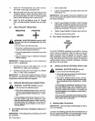
4-11.
HUB
TENSION
ADJUSTMENT
(Figure
4-7)
a
WARNING:
ELECTRIC
SHOCK
can
kill.
Do
not
touch
live
electrical
parts.
Shut
down
welding
power
source,
and
dis
connect
input
power
employing
locko
ut/tag
ging
procedures
before
inspecting
or
install
ing.
Lockout/tagging
procedures
consist
of
remov
ing
input
power
plug
from
receptacle,
pad
locking
line
disconnect
switch
in
open
position,
removing
fuses
from
fuse
box,
or
shutting
off
and
red-tagging
circuit
breaker
or
other
discon
necting
device.
Check
the
hub
tension
by
slowly
pulling
the
wire
toward
S-0037
the
feed
roll.
The
wire
should
unwind
freely,
but
the
hub
tension
should
be
sufficient
to
keep
the
wire
taut
and
pre
vent
backlash
when
the
wire
feeding
ceases.
If
adjust
ment
is
required,
loosen
or
tighten
the
hex
nut
on
the
end
of
the
spindle
support
shaft
accordingly.
4-12.
ELECTRICAL
INPUT
CONNECTIONS
a
o
INPUT
WARNING:
ELECTRIC
SHOCK
can
kill.
Do
not
touch
live
electrical
parts.
Shut
down
welding
power
source,
and
dis
connect
input
power
employing
locko
ut/tag
ging
procedures
before
inspecting
or
install
ing.
Lockout/tagging
procedures
consist
of
remov
ing
input
power
plug
from
receptacle,
pad
locking
line
disconnect
switch
in
open
position,
removing
fuses
from
fuse
box,
or
shutting
off
and
red-tagging
circuit
breaker
or
other
discon
necting
device.
A.
Electrical
Input
Requirements
Operate
the
welding
power
source
from
a
single-phase,
60
Hertz,
ac
power
supply.
The
input
voltage
must
match
one
of
the
electrical
input
voltages
shown
on
the
input
data
label
on
the
unit
nameplate.
Contact
the
local
elec
tric
utility
for
information
about
the
type
of
electrical
ser
vice
available,
how
proper
connections
should
be
made,
and
inspection
required.
OM-113
336
Page
16