


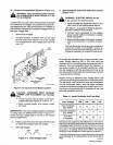
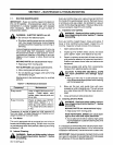
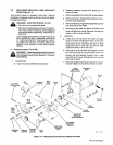

7-2.
REPLACING
DRIVE
ROLL
AND
WIRE
INLET
GUIDE
(Figure
7-1)
As
a
result
of
wear
or
a
change
in
wire
size,
it
may
be
necessary
to
replace
the
drive
rolls
and
wire
inlet
guide.
Proceed
as
follows:
a
WARNING:
ELECTRIC
SHOCK
can
kill.
Do
not
touch
live
electrical
parts.
Shut
down
welding
powersource,
and
discon
nect
input
power
employing
lockouVtagging
procedures
before
inspecting,
maintaining,
or
seivicing.
Lockout/tagging
procedures
consist
of
removing
input
power
plug
from
receptacle,
padlocking
lir~
disconnect
switch
in
open
position,
remov
ing
fuses
from
fuse
box,
or
shutting
off
and
red-
tagging
circuit
breaker
or
other
disconnecting
device.
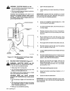
A.
Replacing
Upper
Drive
Roll
a
WARNING:
Read
and
follow
safety
informa
tion
at
beginning
of
entire
Section
7-2
before
proceeding.
1.
Disassembly
a.
Open
and
secure
left
side
access
door.
b.
Release
pressure
spring
from
spring
pin
on
drive
roll
cover.
c.
Remove
cotter
pin
from
drive
roll
cover
pivot
pin.
d.
Remove
pivot
pin,
thereby
freeing
drive
roll
cov
er
from
drive
assembly.
e.
Remove
retaining
ring
and
flanged
bearing
from
one
end
of
drive
roll
shaft.
f.
Push
drive
roll
shaft
out
drive
roll
cover
until
drive
roll
falls
from
cover.
Be
sure
that
key
re
mains
in
slot
in
drive
roll
shaft.
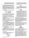
Install
drive
roll
into
drive
roll
cover
with
gear
section
of
drive
roll
facing
the
rear
of
the
cover
(side
facing
motor
insulator).
Be
sure
to
align
clearance
hole
in
drive
roll
with
the
two
shaft
clearance
holes
in
drive
roll
cover.
b.
Align
key
in
drive
roll
shaft
with
keyway
in
drive
roll,
and
route
end
of
drive
roll
shaft
without
re
taining
ring
and
bearing
through
hole
in
rear
side
of
drive
roll
cover,
through
drive
roll,
and
out
front
side
of
cover.
c.
Reinstall
flanged
bearing
and
retaining
ring
re
moved
in
Step
le
onto
end
of
drive
roll
shaft.
2.
Assembly
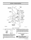
a.
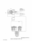
Lower
Wire
Drive
Drive
Roll
Motor
Shaft
And
Key
Wire
Inlet
Guide
Cotter
Pin
Drive
Roll
Cover
spring
Pin
Brush
(2)
Brush
Cap
(2)
Motor
Insulator
Lower
Drive
Roll
Lower
Drive
Roll
Shaft
Self-Locking
Nut
Gun/Feeder
Connector
Opening
Weld
Cable
Terminal
Nut
Drive
Roll
Retaining
Flanged
Cover
Drive
Ring
Bearing
Pivot
Pin
Roll
FIgure
7-1.
Replacing
Drive
Rolls
And
Motor
Brushes
OM-113
336
Page
25