


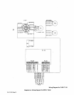

B.
Circuit
Breaker
CB2
a
WARNING:
Read
and
follow
safety
informa
tion
at
beginning
of
entire
Section
7-6
before
proceeding.
Circuit
breaker
CB2
protects
the
24
volts
ac
winding
of
transformer
Ti
from
overload.
CB2
is
located
under
the
access
door.
Should
CB2
open,
the
contactor
W
coil
would
open
thereby
stopping
all
output
from
the
welding
power
source.
If
CB2
opens,
manually
reset
the
breaker.
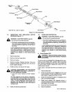
7-7.
THERMAL
OVERLOAD
PROTECTION
Rectifier
SRi
is
protected
from
overheating
by
a
normally-closed
thermostat
TP3
wired
in
series
with
relay
CR1
and
contactor
W
coil
circuit.
Should
overheat
ing
occur,
TP3
would
open
causing
CR1
and
thereby
the
contactor
to
drop
out
(deenergize)
and
the
wire
drive
motor
to
stop,
thereby
stopping
all
weld
output.
If
this
condition
occurs,
it
will
be
necessary
to
allow
a
cooling
period
before
resuming
operation.
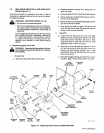
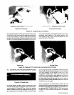
7-8.
PRINTED
CIRCUIT
BOARD
REPLACEMENT
a
WARNING:
ELECTRIC
SHOCK
can
kill.
Do
not
touch
live
electrical
parts.
Shutdown
welding
powersource,
and
discon
nect
input
power
employing
lockout/tagging
procedures
before
inspecting,
maintaining,
or
servicing.
Lockout/tagging
procedures
consist
of
removing
input
power
plug
from
receptacle,
padlocking
line
disconnect
switch
in
open
position,
remov
ing
fuses
from
fuse
box,
or
shutting
off
and
red-
tagging
circuit
breaker
or
other
disconnecting
device.
CAUTION:
ELECTROSTATIC
DISCHARGE
(ESD)
can
damage
circuit
boards.
Put
on
properly
grounded
wrist
strap
BE
FORE
handling
circuit
boards.
Transport
circuit
boards
in
proper
static-
shielding
carriers
or
packages.
Perform
work
only
at
a
static-safe
work
area.
INCORRECT
INSTALLATION
or
misaligned
plugs
can
damage
circuit
board.
Be
sure
that
plugs
are
properly
installed
and
aligned.
EXCESSIVE
PRESSURE
can
break
circuit
board.
Use
only
minimal
pressure
and
gentle
move
ment
when
disconnecting
or
connecting
board
plugs
and
removing
or
installing
board.
WARNING:
ELECTRIC
SHOCK
can
kill.
Do
not
touch
live
electrical
parts.
Shutdown
welding
powersource,
and
discon
nect
input
power
employing
lockout/tagging
procedures
before
inspecting,
maintaining,
or
servicing.
Lockout/tagging
procedures
consist
of
removing
input
power
plug
from
receptacle,
padlocking
line
disconnect
switch
in
open
position,
remov
ing
fuses
from
fuse
box,
or
shutting
off
and
red-
tagging
circuit
breaker
or
other
disconnecting
device.
MOVING
PARTS
can
cause
serious
injury.
Keep
away
from
moving
parts.
HOT
SURFACES
can
cause
severe
burns.
Allow
cooling
period
before
servicing.
Troubleshooting
to
be
performed
only
by
qualified
persons.
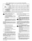
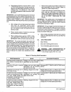
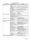
7-9.
TROUBLESHOOTING
a
a
It
is
assumed
that
the
unit
was
properly
installed
accord
ing
to
Section
4
of
this
manual,
the
operator
is
familiar
with
the
function
of
controls,
the
welding
power
source
was
working
property,
and
that
the
trouble
is
not
related
to
the
welding
process.
The
following
table
is
designed
to
diagnose
and
provide
remedies
for
some
of
the
troubles
that
may
develop
in
this
welding
power
source.
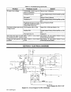
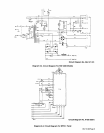
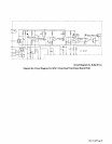
Use
this
table
in
conjunction
with
the
circuit
diagram
while
performing
troubleshoot
ing
procedures.
If
the
trouble
is
not
remedied
after
per
forming
these
procedures,
contact
the
nearest
Factory
Authorized
Service
Station.
In
all
cases
of
equipment
malfunction,
strictly
follow
the
manufacturers
proce
dures
and
instructions.
OM-113
336
Page
28