


d.
Reinstall
drive
roll
cover
and
pivot
pin
into
drive
roll
assembly.
e.
Reinstall
cotter
pin
onto
pivot
pin.
f.
If
installing
or
changing
lower
drive
roll,
proceed
to
Section
7-2B;
otherwise,
reengage
pressure
spring
over
spring
pin
on
drive
roll
cover,
and
close
and
secure
access
door.
B.
Replacing
Lower
Drive
Roll
a
WARNING:
Read
and
follow
safety
informa
tion
at
beginning
of
entire
Section
7-2
before
proceeding.
1.
Disassembly
a.
If
applicable,
release
pressure
spring
from
spring
pin
on
drive
roll
cover.
b.
If
applicable,
pivot
upper
drive
roll
up,
awayfrom
lower
drive
roll.
c.
Remove
self-locking
nut
from
end
of
lower
drive
roll
shaft,
and
remove
drive
roll.
Be
sure
that
key
remains
in
slot
in
drive
roll
shaft.
2.
Assembly
a.
Install
drive
roll
onto
lower
drive
roll
shaft
align
ing
keyway
in
drive
roll
clearance
hole
with
key
in
drive
roll
shaft.
(Drive
roll
must
be
installed
with
gear
section
facing
the
motor
insulator.)
b.
Reinstall
self-locking
nut
onto
drive
roll
shaft.
c.
Adjust
horizontal
position
of
lower
drive
roll
in
or
out
as
necessary.
To
move
the
drive
roll
in
to
wards
the
motor
insulator,
rotate
the
self-lock
ing
nut
clockwise.
To
move
the
drive
roll
out
away
from
the
center
panel
of
the
unit,
rotate
the
nut
counterclockwise.
IMPORTANT:
Be
sure
that
upper
and
lower
drive
roll
gears
are
properly
meshed
and
the
drive
roll
grooves
are
aligned
when
adjusting
horizontal
position
of
lower
drive
roll.
d.
Reengage
pressure
spring
over
spring
pin
on
drive
roll
cover.
e.
If
replacing
wire
inlet
guide,
proceed
to
Section
7-20;
otherwise,
close
and
secure
side
access
door.
C.
Replacing
Wire
Inlet
Guide
1.
Loosen
wire
guide
securing
screw.
2.
Remove
wire
guide
from
drive
housing.
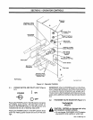
3.
Install
new
wire
guide
through
mounting
hole
in
left
side
of
drive
housing
(see
Figure
7-1).
IMPORTANT:
Wire
guide
should
be
installed
as
close
to
the
drive
rolls
as
possible
without
touching
them.
4.
Tighten
wire
guide
securing
setscrew.
5.
Close
and
secure
side
access
door.
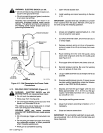
7-3.
DRIVE
HOUSING
REALIGNMENT
(Figure
4-7)
a
WARNING:
ELECTRIC
SHOCK
can
kill.
Do
not
touch
live
electrical
parts.
Shutdown
welding
powersource,
and
discon
nect
input
power
employing
lockout/tagging
procedures
before
inspecting,
maintaining,
or
servicing.
Lockout/tagging
procedures
consist
of
removing
input
power
plug
from
receptacle,
padlocking
line
disconnect
switch
in
open
position,
remov
ing
fuses
from
fuse
box,
or
shutting
off
and
red-
tagging
circuit
breaker
or
other
disconnecting
device.
The
wire
drive
housing
is
made
with
mounting
holes
of
sufficient
clearance
to
provide
adjustment
of
the
wire
guides
up
or
down
in
relation
to
the
drive
rolls.
This
ad
justment
has
been
factory
set,
but
if
readjustment
be
comes
necessary
proceed
as
follows:
1.
Open
access
door.
2.
Loosen
mounting
bolts
and
the
weld
terminal
nut,
securing
wire
drive
housing
to
the
air
baffle.
3.
Slide drive
housing
upward
or
downward
until
the
wire
can
be
fed
straight
through
the
guides
while
seated
in
the
drive
roll.
4.
Tighten
mounting
bolts
and
weld
terminal
nut.
5.
Close
and
secure
access
door.
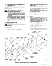
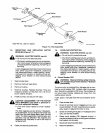
7-4.
REPLACING
HUB
ASSEMBLY
(Figure
7-2)
If
it
should
become
necessary
to
replace
part
or
all
of
the
hub
assembly,
reinstall
the
new
hub
assembly
as
follows:
1.
Slide
the
following
items
onto
the
single
support
shaft
in
order
given:
a.
Fiber
Washer
b.
Brake
Washer
c.
Hub
d.
Brake
Washer
e.
Fiber
Washer
f.
Keyed
Washer
g.
Spring
h.
Flat
Washer
2.
Rotate
hex
nut
onto
support
shaft.
Hex
nut
should
be
rotated
only
until
a
slight
drag
is
felt
while
turn
ing
hub.
3.
Install
welding
wire
according
to
Section
4-13.
4.
Reinstall
retaining
ring
onto
hub.
OM-113
336
Page
26