


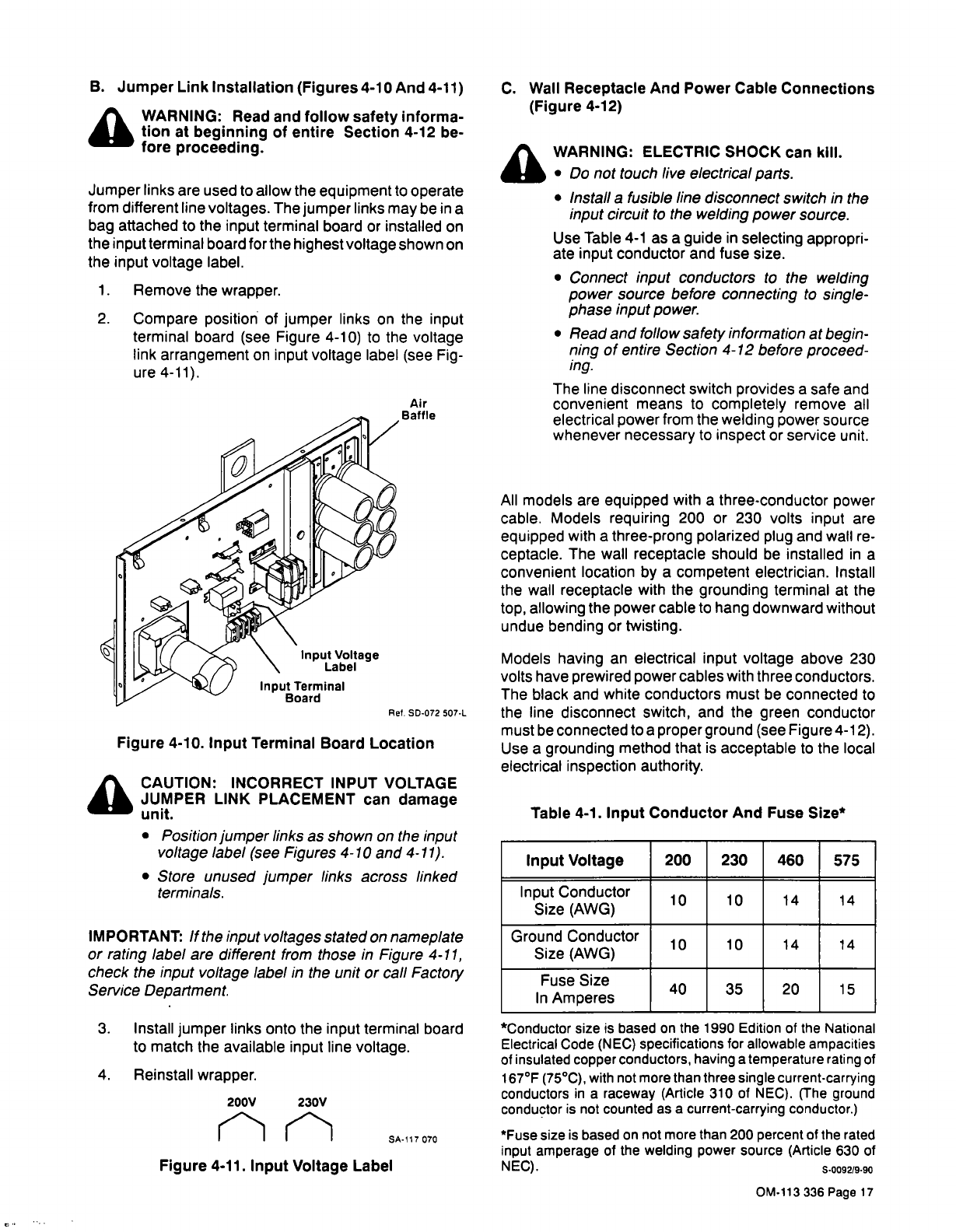
B.
Jumper
Link
Installation
(Figures
4-10
And
4-11)
a
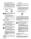
WARNING:
Read
and
follow
safety
informa
tion
at
beginning
of
entire
Section
4-12
be
fore
proceeding.
Jumper
links
are
used
to
allow
the
equipment
to
operate
from
different
line
voltages.
The
jumper
links
may
be
in
a
bag
attached
to
the
input
terminal
board
or
installed
on
the
input
terminal
board
for
the
highest
voltage
shown
on
the
input
voltage
label.
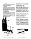
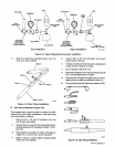
1.
Remove
the
wrapper.
2.
Compare
position
of
jumper
links
on
the
input
terminal
board
(see
Figure
4-10)
to
the
voltage
link
arrangement
on
input
voltage
label
(see
Fig
ure
4-11).
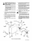
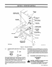
Air
Baffle
a
CAUTION:
INCORRECT
INPUT
VOLTAGE
JUMPER
LINK
PLACEMENT
can
damage
unit.
Position
jumper
links
as
shown
on
the
input
voltage
label
(see
Figures
4-10
and
4.11).
Store
unused
jumper
links
across
linked
terminals.
IMPORTANT:
If
the
input
voltages
stated
on
nameplate
or
rating
label
are
different
from
those
in
Figure
4-11,
check
the
input
voltage
label
in
the
unit
or
call
Factor,
Service
Department.
3.
Install
jumper
links
onto
the
input
terminal
board
to
match
the
available
input
line
voltage.
4.
Reinstall
wrapper.
C.
Wall
Receptacle
And
Power
Cable
Connections
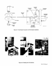
(Figure
4-12)
WARNING:
ELECTRIC
SHOCK
can
kill.
Do
not
touch
live
electrical
parts.
Install
a
fusible
line
disconnect
switch
in
the
input
circuit
to
the
welding
power
source.
Use
Table
4-1
as
a
guide
in
selecting
appropri
ate
input
conductor
and
fuse
size.
Connect
input
conductors
to
the
welding
power
source
before
connecting
to
single-
phase
input
power.
Read
and
follow
safety
information
at
begin
ning
of
entire
Section
4-12
before
proceed
ing.
The
line
disconnect
switch
provides
a
safe
and
convenient
means
to
completely
remove
all
electrical
power
from
the
welding
power
source
whenever
necessary
to
inspect
or
service
unit.
All
models
are
equipped
with
a
three-conductor
power
cable.
Models
requiring
200
or
230
volts
input
are
equipped
with
a
three-prong
polarized
plug
and
wall
re
ceptacle.
The
wail
receptacle
should
be
installed
in
a
convenient
location
by
a
competent
electrician.
Install
the
wall
receptacle
with
the
grounding
terminal
at
the
top,
allowing
the
power
cable
to
hang
downward
without
undue
bending
or
twisting.
Table
4-1.
Input
Conductor
And
Fuse
Slze*
In
put
Voltage
200 230
460
575
Input
Conductor
Size
(AWG)
10 10
14
14
Ground
Conductor
Size
(AWG)
10 10
14
14
Fuse
Size
In
Amperes
40 35
20
15
*Conductor
size
is
based
on
the
1990
Edition
of
the
National
Electrical
Code
(NEC)
specifications
for
allowable
ampacities
of
insulated
copper
conductors,
having
a
temperature
rating
of
167F
(75C),
with
not
more
than
three
single
current-carrying
conductors
in
a
raceway
(Article
310
of
NEC).
(The
ground
conductor
is
not
counted
as
a
current-carrying
conductor.)
*Fuse
size
is
based
on
not
more
than
200
percent
of
the
rated
input
amperage
of
the
welding
power
source
(Article
630
of
NEC).
S~0092/9~90
Input
Voltage
Label
Input
Terminal
Board
Figure
4-10.
Input
Terminal
Board
Location
Models
having
an
electrical
input
voltage
above
230
volts
have
prewired
power
cables
with
three
conductors.
The
black
and
white
conductors
must
be
connected
to
RefS0-072507-L
the
line
disconnect
switch,
and
the
green
conductor
must
be
connected
to
a
proper
ground
(see
Figure
4-12).
Use
a
grounding
method
that
is
acceptable
to
the
local
electrical
inspection
authority.
200V
230V
Figure
4-11.
Input
Voltage
Label
SA-117
070
OM-113
336
Page
17