


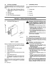

IMPORTANT:
SPW-
1
Spot
Panel
will
not
provide
spot
capabilities
for
the
Spool
gun.
Retain
all
hardware
re
moved
during
this
procedure
for
reinstallation.
All
direc
tions,
such
as
left
or
right,
are
with
respect
to
the
opera-
for
facing
the
front
panel.
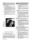
1.
Remove
module
cover
plate
from
upper
right-
hand
corner
of
front
panel.
2.
Locate
wiring
harness
clamped
to
air
baffle.
Re
move
wiring
harness
from
first
clamp
and
careful
ly
pull
end
of
wiring
harness
with
connectors
through
opening
in
front
panel
it
will
come
through
approximately
2
in.
(51
mm).
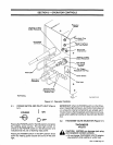
3.
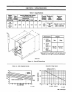
Disconnect
jumpered
connector
from
plug
PLG2.
4.
Connect
receptacle
RC55
from
SPW-1
panel
to
PLG2.
Be
sure
the
connectors
are
locked
togeth
er
(see
Figure
4-3).
5.
Install
SPW-1
panel
into
upper
right
corner
of
front
panel,
and
secure
using
screws
removed
in
Step
1.
a
WARNING:
PRESSURIZED
CYLINDERS
can
rupture
causing
serious
personal
injury
and
loss
of
life;
FALLING
CYLINDERS
can
cause
serious
injury
and
equipment
damage.
Keep
cylinders
away
from
welding
or
other
electrical
circuits.
Never
allow
a
welding
electrode
to
touch
any
cylinder.
Always
fasten
cylinder
securely
to
running
gear
bracket,
a
wall,
or
other
stationary
sup
port.
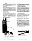
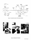
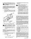
B.
Regulator/Flowmeter
(Customer
Supplied)
(Fig
ure
4-4)
1.
With
the
cylinder
correctly
installed,
remove
cylin
der
cap
(see
Figure
4-4).
Stand
to
one
side
of
the
cylinder
valve,
and
open
the
valve
slightly.
When
gas
flows
from
cylinder,
close
valve.
This
proce
dure
gets
rid
of
any
dust
or
dirt
that
may
have
ac
cumulated
around
the
valve
seat.
2.
The
regulator/flowmeter
must
be
properly
equipped
with
a
stem,
nut
connectors,
and
gasket
for
use
with
either
CO2
cylinders
or
Argon/CO2
cylinders.
IMPORTANT:
A
gasket
should
be
installed
to
prevent
leaks.
Do
not
use
lubricants
or
sealing
agents.
3.
Install
gas
regulator
onto
gas
cylinder
valve;
keep
the
face
of
the
regulator/flowmeter
gauge
in
the
vertical
position,
and
tighten
stem
nut
securely
onto
gas
cylinder.
4.
A
shielding
gas
output
fitting
is
provided
at
the
rear
of
the
welding
power
source
for
making
gas
connections.
Attach
one
end
of
the
gas
hose
to
this
output
fitting.
Attach
other
end
of
the
gas
hose
to
the
regulator/f
lowmeter.
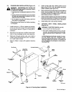
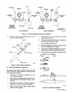
4-6.
WORK
CABLE
ASSEMBLY
A
10
ft.
(3
m)
cable
with
a
lug
attached
to
one
end
is
supplied
with
the
unit.
To
install
the
work
clamp
and
jack
plug
onto
the
cable,
proceed
as
follows:
A.
Work
Clamp
Installation
(Figure
4-5)
FIgure
4-3.
SPW-1
Panel
Installation
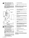
4-5.
SHIELDING
GAS
INSTALLATION
A.
Gas
Cylinder
(Customer
Supplied)
(Figure
3-3)
Secure
gas
cylinder
to
running
gear
using
safety
chain
on
cylinder
bracket.
If
the
running
gear
is
not
to
be
used,
chain
cylinder
to
wall
or
other
stationary
support
to
pre
vent
the
cylinder
from
falling
over
and
breaking
off
the
valve.
1.
Insert
the
end
of
the
work
cable
with
the
terminal
lug
on
it
through
one
of
two
supplied
insulating
sleeves.
2.
Lay
the
work
cable
inside
the
handle
of
the
work
clamp
which
has
the
flattest
inner
surface.
3.
Align
the
smaller
hole
in
the
work
clamp
handle
with
the
hole
in
the
work
cable
terminal
lug.
Se
cure
the
terminal
lug
to
the
work
clamp
with
the
supplied
nut
and
bolt.
4.
Bend
the
tabs
on
the
end
of
the
work
clamp
han
dle
around
the
work
cable.
5.
Slide
the
insulating
sleeve
on
the
work
cable
over
the
work
clamp
handle.
Plug
_....~
PLG2
Receptacle
RC55
SPw-1
._~
Spot
Panel
OM-113
336
Page
12