


Regulator
CO2
Installation
SB-109
492-A
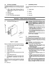
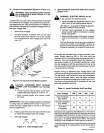
6.
Slide
the
remaining
insulating
sleeve
over
the
other
work
clamp
handle.
Step
3
Figure
4-5.
Work
Clamp
Installation
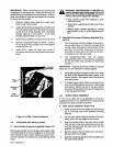
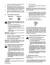
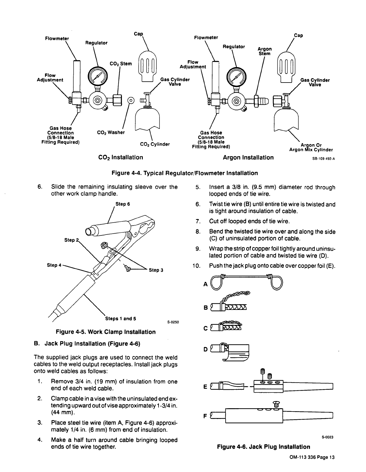
B.
Jack
Plug
Installation
(Figure
4-6)
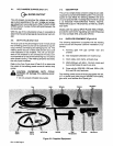
0250
The
supplied
jack
plugs
are
used
to
connect
the
weld
cables
to
the
weld
output
receptacles.
Install
jack
plugs
onto
weld
cables
as
follows:
1.
Remove
3/4
in.
(19
mm)
of
insulation
from
one
end
of
each
weld
cable.
2.
Clamp
cable
in
a
vise
with
the
uninsulated
end
ex
tending
upward
out
of
vise
approximately
1-3/4
in.
(44
mm).
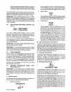
3.
Place
steel
tie
wire
(item
A,
Figure
4-6)
approxi
mately
1/4
in.
(6
mm)
from
end
of
insulation.
4.
Make
a
half
turn
around
cable
bringing
looped
ends
of
tie
wire
together.
5.
Insert
a
3/8
in.
(9.5
mm)
diameter
rod
through
looped
ends
of
tie
wire.
6.
Twist
tie
wire
(B)
until
entire
tie
wire
is
twisted
and
is
tight
around
insulation
of
cable.
7.
Cut
off
looped
ends
of
tie
wire.
8.
Bend
the
twisted
tie
wire
over
and
along
the
side
(C)
of
uninsulated
portion
of
cable.
9.
Wrap
the
strip
of
copper
foil
tightly
around
uninsu
lated
portion
of
cable
and
twisted
tie
wire
(D).
10.
Push
the
jack plug
onto
cable
over
copper
foil
(E).
AU
B~
~
U
FP
S~0023
Figure
4-6.
Jack
Plug
Installation
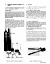
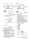
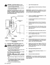
Gas
Hose
Connection
CO2
Washer
(5/8.18
Male
Fitting
Required)
CO2
Cylinder
Gas
Hose
Connection
(5/8-18
Male
Fitting
Required)
Argon
Installation
Argon
Or
Argon
Mix
Cylinder
Figure
4-4.
Typical
Regulator/Flowmeter
Installation
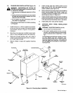
Step
6
Step
Step
4
Steps
1
and
5
OM-113
336
Page
13