


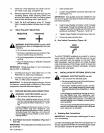
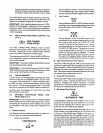
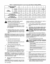
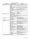
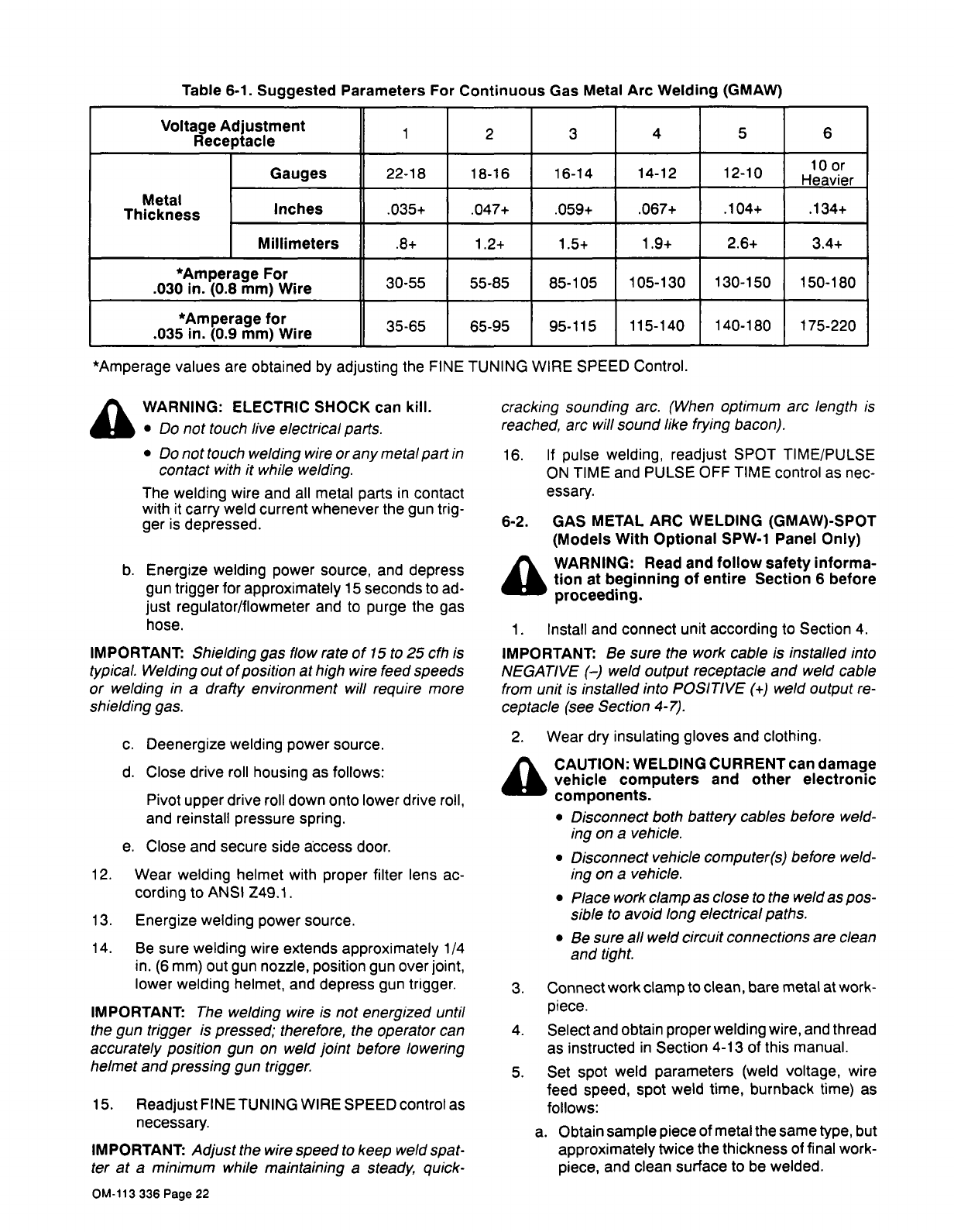
Table
6-1.
Suggested
Parameters
For
Continuous
Gas
Metal
Arc
Welding
(GMAW)
Voltage
Adjustment
Receptacle
1
2
3
4
5
6
Metal
Thickness
Gauges
22-18
18-16
16-14
14-12
12-10
10
or
Heavier
Inches
.035+
.047+
.059+
.067+
.104+
.134+
Millimeters
.8+
1.2+
1.5+
1.9+
2.6+
3.4+
*Amperage
For
.030
in.
(0.8
mm)
Wire
30-55 55-85
85-105
105-130
130-150
150-180
*Amperage
for
.035
in.
(0.9
mm)
Wire
35-65
65-95
95-115
115-140
140-180 175-220
*Amperage
values
are
obtained
by
adjusting
the
FINE
TUNING
WIRE
SPEED
Control.
~
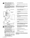
WARNING:
ELECTRIC
SHOCK
can
kill.
cracking
sounding
arc.
(When
optimum
arc
length
is
Do
not
touch
live
electrical
parts.
reached,
arc
will
sound
like
frying
bacon).
Do
nottouch
welding
wire
orany
metal
part
in
16.
If
pulse
welding,
readjust
SPOT
TIME/PULSE
contact
with
it
while
welding.
ON
TIME
and
PULSE
OFF
TIME
control
as
nec-
The
welding
wire
and
all
metal
parts
in
contact
essary.
with
it
carry
weld
current
whenever
the
gun
trig
ger
is
depressed.
6-2.
GAS
METAL
ARC
WELDING
(GMAW)-SPOT
(Models
With
Optional
SPW-1
Panel
Only)
a
WARNING:
Read
and
follow
safety
informa
b.
Energize
welding
power
source,
and
depress
tion
at
beginning
of
entire
Section
6
before
gun
trigger
for
approximately
15
seconds
to
ad-
proceeding.
just
regulator/flowmeter
and
to
purge
the
gas
hose.
1.
Install
and
connect
unit
according
to
Section
4.
IMPORTANT:
Shielding
gas
flow
rate
of
15
to
25
cfh
is
IMPORTANT:
Be
sure
the
work
cable
is
installed
into
typical.
Welding
out
of
position
at
high
wire
feed
speeds
NEGATIVE
()
weld
output
receptacle
and
weld
cable
or
welding
in
a
drafty
environment
will
require
more
from
unit
is
installed
into
POSITIVE
(.4-)
weld
output
re
shielding
gas.
ceptacle
(see
Section
4-7).
2.
Wear
dry
insulating
gloves
and
clothing.
c.
Deenergize
welding
power
source.
CAUTION:
WELDING
CURRENT
can
damage
d.
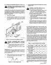
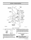
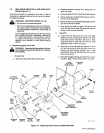
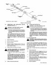
Close
drive
roll
housing
as
follows:
vehicle
computers
and
other
electronic
Pivot
upper
drive
roll
down
onto
lower
drive
roll,
components.
and
reinstall
pressure
spring.
Disconnect
both
battery
cables
before
weld
ing
on
a
vehicle.
e.
Close
and
secure
side
access
door.
Disconnect
vehicle
computer(s)
before
weld-
12.
Wear
welding
helmet
with
proper
filter
lens
ac-
ing
on
a
vehicle.
cording
to
ANSI
Z49.
1.
Place
work
clamp
as
close
to
the
weld
as
pos
13.
Energize
welding
power
source.
sible
to
avoid
long
electrical
paths.
Be
sure
all
weld
circuit
connections
are
clean
14.
Be
sure
welding
wire
extends
approximately
1/4
and
tight.
in.
(6
mm)
out
gun
nozzle,
position
gun
over
joint,
lower
welding
helmet,
and
depress
gun
trigger.
3.
Connect
work
clamp
to
clean,
bare
metal
at
work-
IMPORTANT:
The
welding
wire
is
not
energized
until
piece.
the
gun
trigger
is
pressed;
therefore,
the
operator
can
4.
Select
and
obtain
proper
welding
wire,
and
thread
accurately
position
gun
on
weld
joint
before
lowering
as
instructed
in
Section
4-13
of
this
manual.
helmet
and
pressing
gun
trigger.
5.
Set
spot
weld
parameters
(weld
voltage,
wire
feed
speed,
spot
weld
time,
burnback
time)
as
15.
Readjust
FINE
TUNING
WIRE
SPEED
control
as
follows:
necessary.
a.
Obtain
sample
piece
of
metal
the
same
type,
but
IMPORTANT:
Adjust
the
wire
speed
to
keep
weld
spat-
approximately
twice
the
thickness
of
final
work
ter
at
a
minimum
while
maintaining
a
steady,
quick-
piece,
and
clean
surface
to
be
welded.
OM-113
336
Page
22