


Arcing
causes
the
contact
surfaces
to
become
pitted.
Eventually
continuity
is
lost
and
the
selec
tor
plug
no
longer
works
to
select
output
range.
The
THICKNESS
VOLTS
selector
jack
plug
and
recep
tacles
provide
a
selection
of
heat
input
to
the
weld.
The
higher
the
numbered
receptacle,
the
hotter
the
weld.
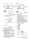
IMPORTANT:
After
installing
selector
plug
into
THICK
NESS
VOLTS
receptacle,
rotate
plug
1/4
turn
clockwise
to
secure
in
place.
When
removing
plug
from
receptacle,
rotate
plug
1/4
turn
counterclockwise
while
withdrawing
it
from
receptacle.
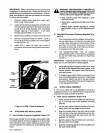
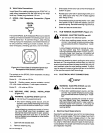
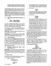
5-3.
FINE
TUNING
WIRE
SPEED
CONTROL
(Fig
ure
5-1)
(~o
FINE
TUNING
-1
WIRE
SPEED
The
FINE
TUNING
WIRE
SPEED
control
provides
selection
of
the
speed
at
which
welding
wire
feeds
into
the
weld.
Rotating
the
FINE
TUNING
WIRE
SPEED
control
clockwise
increases
wire
feed
speed.
The
scale
around
the
FINE
TUNING
WIRE
SPEED
con
trol
is
calibrated
in
percent
and
does
not
indicate
the
ac
tual
wire
feed
speed.
IMPORTANT:
The
FINE
TUNING
WIRE
SPEED
control
may
be
adjusted
while
welding.
IMPORTANT:
In
the
PULSE
mode,
the
FINE
TUNING
WIRE
SPEED
control
must
be
set
at
50
percent
or
less
when
using
THICKNESS
VOLTS
taps
5
and
6.
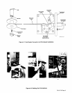
5-4.
FAN-ON-DEMAND~
The
fan
motor
is
thermostatically
controlled
and
does
not
turn
on
with
the
unit
POWER
switch.
The
fan
motor
runs
when
main
transformer
Ti
and/or
rectifier
assem
bly
SR3
are
warm.
Under
normal
loading,
the fan
motor
may
not
run.
The
fan
motor
turns
off
when
Ti
and
SR3
are
cool
or
when
the
unit
POWER
switch
is
turned
off.
Normally-open
thermostats
TP1
and
TP2,
and
relay
CR2
control
the fan
motor.
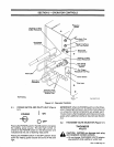
5-5.
OPTIONAL
SPOT/PULSE
PANEL
CON
TROLS
(Figure
5-1)
IMPORTANT:
In
the
PULSE
mode,
the
FINE
TUNING
WIRE
SPEED
control
must
be
set
at
50
percent
or
less.
Exceeding
the
50
percent
control
setting
may
trip
the
circuit
breaker
in
the
motor
control
circuit
stopping
wire
feed.
A.
Selector
Switch
The
Selector
switch
enables
the
operator
to
select
con
tinuous,
spot,
or
pulsed
wire
feed
operation.
1.
Continuous
Position
CONTINUOUS
Placing
Selector
switch
in
CONTINUOUS
posi
tion
and
depressing
the
gun
trigger
feeds
welding
wire
for
as
long
as
the
gun
trigger
remains
closed.
2.
Spot
Position
SPOT
....
Placing
Selector
switch
in
SPOT
position
and
de
pressing
the
gun
trigger
feeds
welding
wire
for
the
length
of
time
set
on
the
SPOT
TIME
control.
3.
Pulse
Position
PULSE
Placing
Selector
switch
in
PULSE
position
and
depressing
the
gun
trigger
feeds
welding
wire
for
the
length
of
time
set
on
the
PULSE
ON
TIME
control.
At
the
end
of
the
pulse
on
time,
welding
wire
stops
feeding
for
the
length
of
time
set
on
the
PULSE
OFF
TIME
control.
The
welding
wire
con
tinues
to
pulse
feed
on
and
off
for
the
selected
times
until
the
gun
trigger
is
released.
The
pulse
option
provides
better
control
of
the
heat
input
to
the
weld
on
thin
gauge
metals,
thereby
decreas
ing
distortion
and
the
likelihood
of
melt-throughs.
B.
Spot
Time/Pulse
On
Time
Control
The
SPOT
TIME/PULSE
ON
TIME
control
enables
the
operator
to
select
from
0.5
to
4
seconds
of
pulse
time
for
spot
operation
or
0.25
to
2
seconds
for
pulse
operation.
Rotating
the
control
clockwise
increases
spot/pulse
on
time.
The
control
scale
is
calibrated
in
percent
and
does
not
indicate
actual
spot/pulse
on
time.
C.
Pulse
Off
Time
Control
The
PULSE
OFF
TIME
control
enables
the
operator
to
select
from
0.25
to
i
second
of
pulse
off
time
for
pulse
operation.
Rotating
the
control
clockwise
increases
pulse
off
time.
The
control
scale
is
calibrated
in
percent
and
does
not
indicate
actual
pulse
off
time.
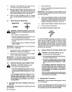
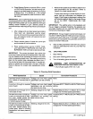
D.
Burn
back
Time
Control
e.~.
~
BURNBACK
TIME
The
BURNBACK
TIME
control
provides
a
means
of
ad
justing
the
time
period
(up
to
a
maximum
of
0
25
sec
onds)
that
the
welding
wire
remains
electrically
ener
gized
after
the
wire
feeding
has
stopped.
By
adjusting
this
control
properly,
the
welding
wire
will
neither
freeze
in
the
weld
puddle
nor
in
the
contact
tube
of
the
gun.
If
the
welding
wire
freezes
to
the
work,
in
crease
the
burnback
time.
If
the
welding
wire
burns
back
into
the
contact
tube,
decrease
the
burnback
time
Ro
tate
the
control
clockwise
to
increase
the
burnback
time,
and
rotate
the
control
counterclockwise
to
decrease
the
burnback
time.
The
scale
surrounding
the
control
is
cali
brated
in
percent
and
does
not
represent
an
actual
burn
back
time.
OM-113
336
Page
20